kipper
New Member
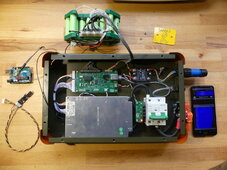
OK, this was going to be me asking advice as to why my BMS died after a few hours of testing but after re-reading the data sheet it seems that my temporary test battery pack made from Li-ion 3.6V (charged to 4.2V) cells might have been too high a voltage. Still, I might as well show my control panel with my BMS 'companion' board to tidy up the installation. The BMS is (was) a JBD AP21S002. the board reads the data from the BMS via RS485, connects to the inverter via an isolated can bus transceiver, makes all the links to the BMS sense inputs to configure it as a 16S unit and controls the heaters via an solid state relay.


The project is located here, there's lots of details and code .

 github.com
The BMS is showing up when the Overkill solar app scans for devices and connects when selected, the correct and stable pack voltage is displayed as well as the 16 cells with their respective voltages, no other data will down load, the 'BMS loading' text seems to correspond with the flashing of the BMS's blue led. No data can be retrieved from the RS485 connection. There is 3.3V on the BMS internal voltage regulator.
Previously when tested on a 10S pack the BMS worked perfectly, it would communicate to the Arduino IDE via the RS485 port, would charge, discharge and balance the cells but after several hours the Bluetooth would randomly drop out which I thought at the time was due to reading the RS485 port at the same time as the blue tooth was pulling data.
My circuit board seems to be working well, I've made a BMS simulator that sends the data that the BMS would normally send when requested, the board also makes the specific links to the voltage sense wires that configure the BMS to a 16S system and the heater relay is controlling by the data received from the BMS.


The project is located here, there's lots of details and code .
GitHub - RustyKipper/BoxOfSunshine: Solar battery to inverter interface
Solar battery to inverter interface. Contribute to RustyKipper/BoxOfSunshine development by creating an account on GitHub.
The BMS is showing up when the Overkill solar app scans for devices and connects when selected, the correct and stable pack voltage is displayed as well as the 16 cells with their respective voltages, no other data will down load, the 'BMS loading' text seems to correspond with the flashing of the BMS's blue led. No data can be retrieved from the RS485 connection. There is 3.3V on the BMS internal voltage regulator.
Previously when tested on a 10S pack the BMS worked perfectly, it would communicate to the Arduino IDE via the RS485 port, would charge, discharge and balance the cells but after several hours the Bluetooth would randomly drop out which I thought at the time was due to reading the RS485 port at the same time as the blue tooth was pulling data.
My circuit board seems to be working well, I've made a BMS simulator that sends the data that the BMS would normally send when requested, the board also makes the specific links to the voltage sense wires that configure the BMS to a 16S system and the heater relay is controlling by the data received from the BMS.
Last edited:


