Yes, you can order a temp sensor.
You are using an out of date browser. It may not display this or other websites correctly.
You should upgrade or use an alternative browser.
You should upgrade or use an alternative browser.
Question about Overkill Solar (4s120a) BMS unit and B- and C- (3) wire configuration.
- Thread starter NCblueridge
- Start date
NCblueridge
New Member
- Joined
- Jul 31, 2020
- Messages
- 154
One other thing with my OK BMS, it has a place for a temp connector but didn't come with one. Is this something I can order somewhere?
Thanks,
William
I found the temp wire and probe, it was on a different side of the board I wasn't looking at..duh.
I also tested it for heat with my heatgun on a setting and it is very precise - room temp is within less than one degree of my thermometer also. I like this! Also, there are actually two sensors, one on the board itself and the external wired sensor. So far I am loving the Overkill BMS and really like the app on my iphone for managing it.
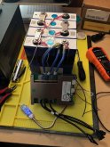
Here's my 105AH 4s with the BMS connected.
Attachments
There is an argument to have the balance leads connected mid-busbar, I know that intuitively you'd think that voltage of two points connected by a big busbar would be equal but when you consider the huge currents these batteries generate, even a small resistance creates a big voltage drop and when you're talking about mili-volts between cells that voltage drop could be material.
If you considered a busbar of 3" to be equivalent to, say, 1/0AWG cable, which has a resistance of 0.0975mΩ per foot or 0.0244mΩ over 3" that's a voltage drop 2.5mV across the busbar if 100A were flowing. Does this matter? Probably not, but it's not something that can be simply dismissed as irrelevant. I would say that it would always be preferable to connect balance leads mid-busbar. Preferable, but not essential.
If you considered a busbar of 3" to be equivalent to, say, 1/0AWG cable, which has a resistance of 0.0975mΩ per foot or 0.0244mΩ over 3" that's a voltage drop 2.5mV across the busbar if 100A were flowing. Does this matter? Probably not, but it's not something that can be simply dismissed as irrelevant. I would say that it would always be preferable to connect balance leads mid-busbar. Preferable, but not essential.
There is an argument to have the balance leads connected mid-busbar, I know that intuitively you'd think that voltage of two points connected by a big busbar would be equal but when you consider the huge currents these batteries generate, even a small resistance creates a big voltage drop and when you're talking about mili-volts between cells that voltage drop could be material.
If you considered a busbar of 3" to be equivalent to, say, 1/0AWG cable, which has a resistance of 0.0975mΩ per foot or 0.0244mΩ over 3" that's a voltage drop 2.5mV across the busbar if 100A were flowing. Does this matter? Probably not, but it's not something that can be simply dismissed as irrelevant. I would say that it would always be preferable to connect balance leads mid-busbar. Preferable, but not essential.
When you say to put the balance leads mid-bus bar, the alternative is what? Locating the balance lead closer to the terminal it is intended to affect?
I would be inclined to put a hole in the bus bar closer to the terminal that is going to be affected for two reasons:
1. It is sort of self-documenting that the lead is affected that terminal. Maybe not a big deal but it might keep me from confusing myself.
2. It gets the balance lead out of the way in case you want to put some protective coating on the middle of the bus bar.
That can't be right.
I'm finishing up my battery pack build and purchased an Overkill Solar 4s120a BMS (with the bluetooth feature). It looks to be well built.
Is there a reason there are (3) wires for the blue (B-) and black (C-) instead of typically (2) that I see on some other BMS's? I assume all (3) are needed.
I think, the stock factory version of this BMS comes with two wires but solder pads for three, and Overkill orders or adds a third (which is great).
If you look at an ampacity table (like this one) 200*C 10 AWG, is good to 70A (so ~140A combined if current is evenly distributed). That is technically above the 120A rating of the BMS, so is technically sufficient, yet leaves little margin. Adding a third wire provides some safety overhead, and fault tolerance (if one connection is bad or goes bad, 2 can carry the full load).
NCblueridge
New Member
- Joined
- Jul 31, 2020
- Messages
- 154
I think, the stock factory version of this BMS comes with two wires but solder pads for three, and Overkill orders or adds a third (which is great).
If you look at an ampacity table (like this one) 200*C 10 AWG, is good to 70A (so ~140A combined if current is evenly distributed). That is technically above the 120A rating of the BMS, so is technically sufficient, yet leaves little margin. Adding a third wire provides some safety overhead, and fault tolerance (if one connection is bad or goes bad, 2 can carry the full load).
That makes sense, I recently ordered another OK BSM for the 2nd system I am starting to build and upgraded the wiring to 8AWG wires in case I go with a larger inverter at some point on a 12 volt system.
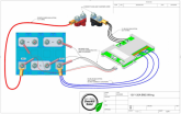
The full manual on their website shows the 4th wire connected to the fourth cell negative (instead of 3rd cell positive), which is adding some additional confusion for me. Can someone more technical than me explain why they would do it this way?
View attachment 22939
Answering my own question to help out anyone else that is confused by this. I emailed overkill and he basically told me it doesnt matter which post you connect to (positive or negative) as long as it is essentially 1 wire per bus bar.
Ampster
Renewable Energy Hobbyist
And to further clarify since there are 5 wires and 3 buss bars on a typical 4 cell build. The first wire which is usually black is put on negative terminal. Wires 2, 3 and 4 are put on buss bars in sequence and wire 5 is put on positive terminal.it doesnt matter which post you connect to (positive or negative) as long as it is essentially 1 wire per bus bar.
Similar threads
- Replies
- 2
- Views
- 356
- Replies
- 15
- Views
- 893
- Replies
- 5
- Views
- 338


