heavy-impact
New Member
- Joined
- Apr 28, 2020
- Messages
- 71
If you have one of these off grid inverters and the low voltage cutoff activates out of spec or you just want to adjust the low voltage cutoff lower or higher you can do this mod. You will need a few inches of 30 gauge wire and a 10K trimmer pot, (I like the 15 turn ones) and a soldering iron with small tip. It helps to have a magnifying visor and a hot glue gun.
Disconnect the inverter from any power.
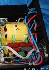
Remove the cover from the inverter.
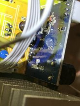
Locate the voltage regulation board just in front of the short heat sink.
Remove the R11 resistor with a soldering iron and tweezers.
Solder a couple inches of wire onto the center leg and either outer leg of the trimmer pot. Doesn't matter which outside leg just use one or the other.
Connect a ohm meter to the trimmer center leg and whichever outside leg you plan to use and set the trimmer to 5000ohm.
Solder the two wires from the trimmer pot to the R11 solder pads where you removed the resistor.
If you have a benchtop power supply you can power the inverter from it to set the low voltage cutoff using the trimmer, otherwise set it with a low battery.
Lower the trimmer resistance to lower cutoff voltage. Increase resistance to raise the cutoff voltage.
I put hot glue over my alarm because I hate it and don't need it.
If you're not comfortable doing this type work then pay someone else to do it.

.jpg")
.jpg")
Disconnect the inverter from any power.
Remove the cover from the inverter.
Locate the voltage regulation board just in front of the short heat sink.
Remove the R11 resistor with a soldering iron and tweezers.
Solder a couple inches of wire onto the center leg and either outer leg of the trimmer pot. Doesn't matter which outside leg just use one or the other.
Connect a ohm meter to the trimmer center leg and whichever outside leg you plan to use and set the trimmer to 5000ohm.
Solder the two wires from the trimmer pot to the R11 solder pads where you removed the resistor.
If you have a benchtop power supply you can power the inverter from it to set the low voltage cutoff using the trimmer, otherwise set it with a low battery.
Lower the trimmer resistance to lower cutoff voltage. Increase resistance to raise the cutoff voltage.
I put hot glue over my alarm because I hate it and don't need it.
If you're not comfortable doing this type work then pay someone else to do it.