diy solar

diy solar

About to Install 48V System - Feedback wanted

off-grid-mitch

New Member
Joined
Oct 5, 2020
Messages
11
Hi all! Everyone's posts here have been super helpful while I've been planning my off-grid setup. I've purchased most things (hopefully I haven't made too many bad decisions) and am getting ready to wire it all together.

A little background:
I recently purchased a house completely off-grid. The current setup is 12v with wimpy panels and lead-acid batteries. After a lot of reading I decided to go with 48v LiFePO4.


8 Panels (https://a1solarstore.com/axipremium-x-hc-400w-mono-hc-large-cells.html)
400W 48.81VOC

Wired 4 sets of 2 in series to 96vdc @ 38.4amp
Wired 20’ to charge controller using 8 AWG

Charge Controller
Max OOC: 125V
Charging Load Current: 40A


2 Batteries (https://bigbattery.com/product/48v-lifepo4-powerwall/)

48v 104 AH (each)
Connected with 6 AWG (https://bigbattery.com/product/anderson-sb175-connectors/?attribute_type=SB175+Parallel+Cable)
Wired 20’ to Inverter using 4/0 AWG (overkill? It will get below freezing where the inverter is)

Inverter (https://www.amazon.com/gp/product/B074BQJRFF/ref=ppx_yo_dt_b_asin_title_o00_s00?ie=UTF8&psc=1)
3000W pure sine 48V


Questions

  • Will what’s going into my charge controller charge the batteries at that rate? Is it overkill?
  • Is it crazy to use such a cheap inverter?
  • Can I use this charger (https://bigbattery.com/product/48v-15a-dc-charger/) for the batteries? I’ve tried to find LiFePO4 specific chargers but I’m not exactly sure what I should be looking for or how much amperage is ok
  • What size fuses should I put where?
  • I wire the ring terminals from the Battery Paralleled to bus bars, which are also wired to the charge controller and inverter?
 
What do you need to power with the inverter? Surge current of induction motors (pumps, air conditioners) are the key. Fridge will be small enough that inverter can handle it.
A full data sheet would tell you how much power it consumes under no-load, important given moderate PV production.

I like big heavy things.

Main fuse on battery should handle continuous load current, size 25% over that. It should have an interrupt rating higher than short-circuit current of the batteries (thousands of amps). I use class-T, which can interrupt 20,000A. The smaller ANL fuses are good for a car battery, not a big battery bank.

Your PV panels are 2s4p. Each of the four strings should have a fuse (or breaker) the size shown on label of panel.

40A charge controller should have 50A fuse.
 
[see above]
The current inverter is 2k and we've been fine except the startup of the fridge is hard on the 12V system. No air conditioner to worry about, and the well pump will be getting the old house 12V system instead of turning on the generator (probably will upgrade the inverter and pass down the cheap amazon 48v inverter and wire the 12v batteries to 48 sooner rather than later). The idea is to go with a 3k inverter for now, and upgrade quite a few things over the next several years.

I really appreciate all the advice on fuses. Just to double check because as of 2 months ago I'm complete newb on hardware electronics - the 50A fuse on the controller goes from the combined panels to the controller, correct? And the main fuse on the battery is between the batteries and the bus connected to the inverter and controller?

Should my focus at this point be on getting more panels and keeping an eye on surge current?
 
50A fuse goes in the wire from batteries to charge controller. You said it is 40A (max charge current?) so 25% over (avoid nuisance trips) use 50A fuse. Wire of course needs sufficient ampacity; 8 awg might do it but 6 awg would be good.

Every (positive) wire from the battery needs a fuse that would blow before wire burns out. Locate fuse at battery end of the wire.

Each PV string needs a fuse because if a string shorts or fails (e.g. bypass diodes fail), the other three strings dump too much current into it.

If that charge controller puts 40A into a 48V (59V max?) battery, that is 2000W to 2400W.

8 panels 400W STC is 3200W. Occasionally they will produce that, typical peak 2700 to 2900W. So your charge controller won't deliver all that to the battery. You're thinking of more panels? Need a larger or second charge controller.

If you orient half the PV panel strings 90 degrees different, e.g. 10:00 AM vs. 4:00 PM sun, peak power will be 0.7 times as much, bringing these panels down within range of the charge controller.

Battery min voltage is 40V, so consider that and efficiency of inverter to size fuse. If 100% efficient, 3000W would be 75A. If 90%, 83A. So 100A fuse is reasonable. Maybe go larger if you already know what inverter you want to upgrade to.

Figure out what you want to power, and how long (Wh/day) first, so you know how many panels you need and what inverter to look for.
And yes, it is kind of silly buying a $300 inverter to power off your $3400 worth of batteries!

I see listings for Sunny Island 6048 (what I use) for about $2200 including shipping. 120VAC, 5750W continuous, 11kW surge, 140 pounds
 
8 panels 400W STC is 3200W. Occasionally they will produce that, typical peak 2700 to 2900W. So your charge controller won't deliver all that to the battery. You're thinking of more panels? Need a larger or second charge controller.
Would each charge controller go to a separate battery, or still to the same bus bar? I'd probably have to check how much the BMS on each battery can handle, but could that be doubled at the parallel connection or have to be split to each LiFePO4 battery?
If you orient half the PV panel strings 90 degrees different, e.g. 10:00 AM vs. 4:00 PM sun, peak power will be 0.7 times as much, bringing these panels down within range of the charge controller.
This is something I've been considering since we use most power during the day charging devices and running computers and monitors for work. Is there literature somewhere on how to calculate this? I am worried tilting them towards the rising and setting of the sun would decrease efficiency and negate the benefits of it. I currently only have 6 panels, but the charge controller can handle 8 voltage and amp wise so that's what I've been basing all my measurements off of for when I increase PV count. Should I orient the 6 straight south to try and hit that 2400W charge controller capacity?
Figure out what you want to power, and how long (Wh/day) first, so you know how many panels you need and what inverter to look for.
And yes, it is kind of silly buying a $300 inverter to power off your $3400 worth of batteries!

I see listings for Sunny Island 6048 (what I use) for about $2200 including shipping. 120VAC, 5750W continuous, 11kW surge, 140 pounds
I will definitely look into that one. I'm nervous about needing to replace the charge controller so I'm still planning on using the cheap inverter first because the all-in-ones look tempting. If I have the proper fuses and low voltage cut-off in place, is there any worry of damaging other components, or just the risk of the inverter being shitty and/or breaking?
 
All charge controllers go to one battery bank. They may have a data link to talk to each other and to the inverter. Or not.

You can find an on-line panel orientation calculator, compare what it shows for an array having ideal Southern orientation with the contemplated orientation(s), and add the results. There will be a power reduction vs. optimum angle. But panels are cheaper than most other parts of the system, and several benefits to doing this.

Some equipment has multiple MPPT inputs. if not, penalty for paralleling two identical strings of different orientations is a couple percent.

If hitting 2400W (full battery) or 2000W (empty battery) SCC capacity means you sometimes exceed that, then you miss out on the clipped production.

Multiple orientations means reducing cycling of battery, also entering evening without having discharged it as much. Plenty of reasons I see to give panels multiple orientations into a single SCC.

Some cheap inverters commit Hari-Kari when they are ashamed of failing to start a motor.
Low voltage would kill a battery. BMS is last line of defense, but should never have to step in.
Over-charging is another way to kill battery (and worse.)

A problem you aren't near yet is excessive charge rate. Not sure about yours, but I hear 0.5C is a maximum for some lithium.
That is something I had to set parameters for, because my PV could exceed 0.5C and my AGM are (probably) best at 0.2C or 0.1C; the vendor has only published what it can accept but not what it prefers.
 
Battery min voltage is 40V, so consider that and efficiency of inverter to size fuse. If 100% efficient, 3000W would be 75A. If 90%, 83A. So 100A fuse is reasonable. Maybe go larger if you already know what inverter you want to upgrade to.
Another question to double check, this fuse should be class-T to be safe, do I need a 100amp both between the batteries and the bus bar and the bus bar and the inverter or is that overkill? If I have a 40amp fuse from the charge controller to bus bar and 100amp from bus bar to batteries should I be fine to wire the inverter without one?

My naivety is showing again, but if they're all connected on the bus bar, the 40amp won't blow during current surge (fridge and microwave for example) because the current is being "drawn" through the inverter 100amp fuse connection, correct?
 
Generally don't need two fuses in series, unless the second one is smaller value to protect smaller wire, e.g. going to charge controller.
Alternatively, could be separate branches rather than in series, so long as each fuse is a type capable of interrupting maximum short circuit possible from the battery.
(In a household breaker panel, the main breaker can interrupt 22kA from the utility. Branch breakers downstream of it can only interrupt 10kA. Before they catch fire the main breaker will trip; after that, ruined breakers need to be replaced.)

You could have a separate 100A fuse for each battery, if their wire can handle 100A and inverter wire can handle 200A. That way (if battery can deliver the current), you can operate with one battery disconnected.

Correct, with only charge controller connected to 40A fuse, current drawn to start fridge or microwave doesn't go through it.
If charge controller can deliver 40A, then fuse should be 50A (and wire ampacity too) because we allow 25% margin to keep it from blowing on a hot day. A fuse is just a device that heats up, and at some point enters thermal runaway. Thermal breakers do too.

Class T seems to be the best I've found, able to interrupt 20,000A DC. I don't know what your batteries can deliver into a dead short. I think my 405 Ah AGM can deliver 16000A based on somebody's test of a different brand 100 Ah AGM delivering 4000A. Class T is expensive, but not unaffordable. I've spent about $160 for two with fuse holders I installed on my batteries, and $120 for two more I'm going to use for my grid connection (because fuses have higher performance than breakers, 200kA for AC)
 
At the moment I see them for $2500 and up. One posting is $4999.99 for two. Doesn't say, "or offer" but you could message him.

Also many hits searching for Solar Trailer, most DC Solar bankruptcy trailers. Could inquire of those sellers if they have individual Sunny Islands.


Searching with Google for Sunny Island site:craigslist.org I see some. Here's an interesting one:


He offers a used Sunny Island for $2000. Or for $3000 includes a Sunny Boy 6000 and a Smartformer (auto-transformer) which would be a good bundle.
 
Here's a listing, two used SI6048 for $3000 starting bid or make offer.


Says pickup only, but maybe he could just strap them to a pallet, and you dispatch a truck.
 
Here's a listing, two used SI6048 for $3000 starting bid or make offer.


Says pickup only, but maybe he could just strap them to a pallet, and you dispatch a truck.
Found this listing: https://www.ebay.com/itm/SMA-SUNNY-...322694?hash=item28a0d9d6c6:g:xWQAAOSwwSpfvIfH

When looking at the spec sheet, it says: Rated input voltage / DC voltage range 48 V/41 V – 63 V 48 V/41 V – 63 V
I misread it actually says: Rated input voltage / AC input voltage range 120 V/80 V – 150 V 120 V/80 V – 150 V

I can't find DC inputs anywhere on the data sheet.
 
Last edited:
The Sunny Island inverter is for a nominal 48V battery. It does not connect directly with PV panels.

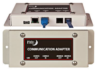
You can "DC couple" the panels with a charge controller. There is a communication link for Midnight Classic.
But the better way to go is AC coupled. If you get a Sunny Boy grid-tie inverter, it will see the grid created by Sunny Island.
(most Sunny Boy work, some very old ones don't. There is a list of supported models.)
What is the communication interface between the SMA 6048-US and the Midnite Classic? I can't seem to figure it out.

Also, if you go DC coupled, how does the power transfer work? I expect that if the CC provides power when the battery is full, then a grid-tied inverter should start drawing power and then send it to the grid, but I'm nervous that I'll end up overcharging the battery instead. Would you need to set the voltage in the CC above the "Full" voltage level of the battery?
 
The only time you would set CC voltage above "Full" battery is if
1) No communication interface is used
2) You want Sunny Island to export power to utility grid from DC coupled PV panels
In that case, Sunny Island draws current from the charge controller to pull voltage down to desired level and dumps power into the grid.
If grid is down, I presume this holds the batteries at higher voltage than desired.

Otherwise, CC tries to hold battery at desired voltage and Sunny Island draws any current needed for AC loads, so charge controller delivers more current.

Here's a retailer link for the SMA/Classic interface. Can't open Midnight's page for it right now.


With the interface, battery voltages and charging phases are under the control of Sunny Island. If communication lost (e.g. Sunny Island turned off or cable disconnected), probably Classic defaults to relatively safe voltages, at least SIC40/SIC50 does.

No danger of overcharging, but could charge at excessive rate if PV adds up to more than 0.2C or whatever battery should get. So limit PV.

I read from another poster that using a BMS which communicates with Sunny Island such as REC, charging voltage is adjusted by BMS in order to adjust current. So that setup may work particularly well, even with large PV array. (But I'm just using AC coupled for my home system.)
 
Just looping back to this thread to share my adventures:

Per the post above by Hedges I bought the communications adapter and setup panels (32 x 240w) along with 2 midnite classics. This allowed my SMA 6048-US to see the incoming power, however I was finding that my power was strangely low. I finally figured out that the inverters were telling the CC's to limit their incoming power so I was losing potential power from my panels. To work around this I unplugged the communications adapter and turned up the voltages on the CC's at which point I was receiving full power. Unfortunately the inverters only saw the high voltage and exported most of the power to the grid (didn't confirm that it was all exported) which resulted in my BatSoc reading ~50% last night even though my batteries were ~90% full. I woke up this morning with the power out and had to scramble to read the emergency shutdown section of the manual to get everything back up (was set to 20%). It was quite an adventure for the morning of a school day!
 
32 x 240W = 7680W
7680W/48V = 160A

SI has a parameter for charge current, I thought default was 0.55 x battery capacity (0.55C charge rate), which would be excessive for lead-acid that it is default for. (Different setting for charge from grid.)

What is your battery capacity, and what is SI's max charge current setting?
It may be that with a different current setting, you will get the charge current you want.

SI was exporting power to grid? I think that means it wants battery voltage to be lower than what Midnight is putting out. I thought that should only happen after battery is fully charged. Could it be Midnight was trying to charge battery, but SI was trying to pull it down to float voltage?
 
I get nowhere near that power output. 20 panels fast East-ish and 12 panels face West-ish (each orientation on different CCs). The panels are used poly panels from EBay ($30 each). In hindsight I didn't realize how expensive the mounting brackets would be, so I really should have bought fewer panels of better quality.

However, it is an interesting point. BatCpyNom is 624Ah. I have BatChrgCurMax set to 75A, even though I can handle a lot more. I set it low because I wanted to limit inflow current from the grid as I might be simultaneously using a lot of electricity and I don't really need to charge fast. InvChrgCurMax is set to 50A.

I've actually tried several things to address this. I was having some partial shading so over the weekend I shifted panels around to eliminate that. I also originally had the East and West facing panels tied together (strings of 4) and would regularly see 80A to the battery, but I had also limited the CC to 80A. This same CC now has just the East facing panels and never exceeds ~55A.

One thing that I noticed recently is that the CCs undergo a state change and that seems to correlate with a drop in current, but I haven't found a pattern yet.

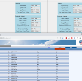
Here's a screenshot around 11a after I experienced a drop-off. Left side is East facing and has transitioned to Float. Right side is West facing and doesn't have full sun yet (CC poll time set to 2s). Bottom is the Sunny Webbox. Currently I see a TotSicBatCur limit of around 70A, but tends to drift around 60A.

1617135688218.png

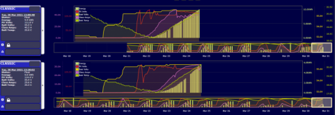
Here is the mymidnite interface with top being East and bottom being West (no clouds today). You can see that the top dropped off 10:45a and transitioned from Absorb to Float (even thought he SI was in float the entire time). In the bottom graph the transition is from Bulk MPPT to Float around the same time but the drop only occurs at 1p with no transition.

1617135892936.png

Anyway, it's still a mystery. I can see that I'm losing a lot of generation and that it is held off by the inverter even while still feeding the grid. I do suspect that there is a grid limit somehow of maybe 2000W, but I do see it vary quite a bit throughout the day.
 
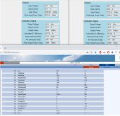
Just to reinforce my point, I unplugged the com adapter around 1:30p and manually set the CC voltages higher at which I point the power immediately jumped back up. The inverters detected the high voltage and started sending excess power to the grid (around 80A), but then my BatSoc started to drop like a rock. Here's right after I unplugged:

1617142006947.png

An hour later I plugged back into the com adapter and power immediately dropped. You can see clearly in the graph that around 1:30p we return to a very nice full power curve, and then an hour later I plug back in and get a huge drop.

1617142198543.png
 

Attachments

  • 1617142173349.png
    1617142173349.png
    123.9 KB · Views: 2
Back
Top