diy solar

diy solar

Will this work for pre-charging inverter capacitors?

Astronom, I'm afraid we are getting away from the question of whether to leave the resistor inline after the caps have charged. I believe FilterGuy is correct but for a different reason altogether.
Indeed, then I would like to try to explain my point further, as we did not understand the same stuff from the posts 71 and 78.

While it is true that two parallel wires are commonly used to increase the equivalent gauge that is not relevant here as we are discussing a circuit with one leg as a low resistance wire and the other leg as a resistor. True but not relevant.
Whichever the resistance of 2 legs of a circuit (even if they are very different as in this case), the total equivalent resistance of the circuit comprising the two legs in parallel will be lower than each resistance of both legs. As a thought experiment, you can consider the large diameter main wire like many (call that N) small diameter wires that are in parallel. You could chose this "small" diameter such as the N imaginary small wires have a resistance equal to the one of the resistor we add in parallel to them. You get then the equivalent of a large wire composed of N+1 small wires. Then the total circuit behaves the same as if there was just one large diameter wire, very slightly larger than the wire that you put in parallel to the resistor in the first place. And I guess we agree that a larger wire has lower Joule effect heat dissipation.

My original concern was that leaving a resistor in a circuit after it is no longer needed is a waste of energy as some portion of whatever current flows through it will be converted to heat. This is also true but not relevant.
This is a point I disagree with in this case. You would be right if you write "leaving a resistor in series", because then indeed the total equivalent resistance of the circuit would be the main wire + the resistor, therefore higher Joule effect power will be dissipated. Here we leave a resistor in parallel to the main circuit, thereby decreasing the equivalent resistance and therefore decreasing Joule effect power.

The relevant point FilterGuy made is that very little current will flow through the circuit leg with the resistor in it. This is likely to be so insignificant of an amount that you can basically ignore that leg of the parallel circuit. This I believe to be true and relevant.
That's not exactly the point he made but I may be wrong (in which case please correct me @FilterGuy). It's true that some power will be dissipated through the resistor if it's left in parallel to the main wire. But because the current that is going through the resistor leg doesn't go through the main wire leg, the power dissipation in the main wire will in turn decrease. This decrease will more than offset the increase of dissipated power in the resistor. In part because Joule effect scales with square of intensity, therefore a small variation of intensity in for a high initial intensity has a larger effect on Joule power dissipation than the same variation for low initial intensity.

Yes the total variation of dissipated power will be insignificant, but it will be a decrease nonetheless, not an increase as it seems you are advocating.

I have ordered a resistor which should get here in a couple days. At that time I will charge the caps and measure any current after that to confirm the hypothesis but I expect any measurable current in the resistor side of the circuit to be insignificant. I will report back either way.
I'm not sure it's the right experiment to do. There will be for sure some current in the resistor, whether you can measure it or not. But if you want to know the full power dissipation of the circuit you also have to measure the current through the main wire, which will be a bit lower than for the same main wire without the resistor in parallel (again you might not be able to measure the difference). So even if you find out that the resistor dissipates let's say 1W, actually you should also be able to measure that the main wire dissipates a bit more than 1W less than before. But this will be quite hard to measure as the current difference will amount for a super tiny fraction of the full current.
 
Well I am likely in over my head here then. If what you say is true then shouldn't I be able to put a bunch of resistors in parallel and decrease power consumption?

While I think I understand parallel circuits I am not getting how a bunch of resistors in parallel would decrease total power consumption of the system. I am not trying to argue, just to learn. Thanks
 
If what you say is true then shouldn't I be able to put a bunch of resistors in parallel and decrease power consumption?

Yes exactly, that's the beauty of it :) If you take a simple case where both resistors are the same, then P = R*I^2 if you only put one resistor, and P = (R*(I/2)^2)+(R*(I/2)^2) = (R*I^2) / 2. That's actually also how you can prove too that 2 resistors in parallel that have the same resistance are equivalent to one resistor with half the resistance. The full formula for equivalent resistance for 2 different resistances in parallel is as follow : 1/Req = 1/R1 + 1/R2 (this is what @FilterGuy used at the end of post 78).

A note though:
Here all this reasoning works because was is constant along the circuit is the current (it's determined by how much the inverter sucks). The voltage drop through a resistor is proportional to the current (U = R*I) and will be reduced as you add some resistors in parallel (because the intensity gets distributed over all of them, thereby decreasing the voltage drop through the resistor).
In another situation where the voltage is constant across the resistors put in parallel (for instance if you have resistive loads directly connected to the terminals of your battery), then because I = U/R each resistor added in parallel will pump a given constant current, which add up in the end, therefore increasing the total power consumption.

Hope this clarifies all this, don't hesitate if something looks fishy though!
 
I'm not aware of any autonomous circuit that would accomplish this task off the shelf. A SPDT relay with the charging circuit on the NC pin and the direct circuit on the NO pin & energizing the relay from the inverter DC + In which will be low till the caps are charged. The inverter caps will keep the relay energized during the switch and till the caps are discharged.
If the caps are already charged (momentary ON>OFF>ON) the relay stays energized. The inverter caps will be discharged via the relay coil once DC inverter power is interrupted.
I'll try to diagram in Dia.
 
The part I'm not getting is how people are charging the caps w/o turning on the inverter. I assumed you had to turn it on to close the circuit. Do they typically have a way to charge w/o the inverter switch being flipped? I suppose one could easily measure. But, I'm in no hurry to play with a perfectly working inverter that is currently on all the time.

Hope this clarifies all this, don't hesitate if something looks fishy though!

Can you increase both power consumption and efficiency by putting two frozen cod filets in parallel?
 
Well I am likely in over my head here then. If what you say is true then shouldn't I be able to put a bunch of resistors in parallel and decrease power consumption?

While I think I understand parallel circuits I am not getting how a bunch of resistors in parallel would decrease total power consumption of the system. I am not trying to argue, just to learn. Thanks

There are two key points.
1) Adding resistance in parallel *reduces* the resistance.
2) With the exception of the loads, all resistance in the system is generating heat and wasting energy.

The key is that lowering resistance will reduce the wasted power consumption and improve the system efficiency. ALL the wires in the system generate heat when current goes through them. That is wasted energy. (Even if they are not warm to the touch, they are generating some small amount of heat) If I add another wire in parallel, the resistance is reduced and they generate less total heat so there is less wasted energy.

I'll make up some numbers to try to illustrate the point.

My load draws 10 Whr
Assuming my inverter is 90% efficient, it has to draw 11 Whr to provide the 10Whr (1 watt hour 'wasted' because it did not do anything useful for you).
If I have a lot of resistance over the wire from the battery, it might heat up and burn .5 watt hours (another .5 watt hour wasted).

The total watt hours drawn from my battery is 11.5 watt hours even though I only used 10 watt hours in the load. If I can find ways to reduce the waste, I have to generate less and my batteries last longer on a charge. I can never get to 100% efficiency but I try to improve it where it is practical.

This is a good conversation for educational reasons, but lets all keep in mind that in the particular case we are talking about the difference is so small it would be difficult to measure.
 
The part I'm not getting is how people are charging the caps w/o turning on the inverter. I assumed you had to turn it on to close the circuit. Do they typically have a way to charge w/o the inverter switch being flipped? I suppose one could easily measure. But, I'm in no hurry to play with a perfectly working inverter that is currently on all the time.

A couple of important points
  • Not all inverters have on-off switches (Particularly the smaller ones)
  • The on-off switch on the inverters are typically after the capacitors (they don't want to deal with the in-rush current either :))
1578076559606.png
 
A couple of important points
  • Not all inverters have on-off switches (Particularly the smaller ones)
  • The on-off switch on the inverters are typically after the capacitors (they don't want to deal with the in-rush current either :))
View attachment 4410
Next time I have to do it I'll use my meter to check while inverter is off.
 
The part I'm not getting is how people are charging the caps w/o turning on the inverter. I assumed you had to turn it on to close the circuit. Do they typically have a way to charge w/o the inverter switch being flipped? I suppose one could easily measure. But, I'm in no hurry to play with a perfectly working inverter that is currently on all the time.


Can you increase both power consumption and efficiency by putting two frozen cod filets in parallel?
Every inverter I have ever seen sparks when connecting the battery... every one.
And I have NEVER hooked up a battery with the inverter turned on.
 
I'm not aware of any autonomous circuit that would accomplish this task off the shelf. A SPDT relay with the charging circuit on the NC pin and the direct circuit on the NO pin & energizing the relay from the inverter DC + In which will be low till the caps are charged. The inverter caps will keep the relay energized during the switch and till the caps are discharged.
If the caps are already charged (momentary ON>OFF>ON) the relay stays energized. The inverter caps will be discharged via the relay coil once DC inverter power is interrupted.
I'll try to diagram in Dia.
Here is a drawing to look at re a means to charge & then connect.
Testone.jpg
The initial current flows through R1 till the voltage drop across R1 reduces allowing RL1 to energize. The Inverter caps & C1 supply the needed potential to keep the relay energized till the NO contact closes. The completed circuit keeps RL1 energized till the BMS or SW1 opens the circuit. R2 provides a delay in energizing the relay by shunting around C1 in its late charging phase. R1 may want to be 30Ω or a bit more & R2 50KΩ or so. The Battery voltage would also figure into determining those resistor values.
 
To be honest, I think whatever circuit we come up with, we'll not find a cheap way of automatically switching hundreds of amps. Most relays/contactors I've looked at are hundreds of pounds even for the cheap ones. Switches are in the tens of pounds range.
 
EDIT: WARNING: After further investigation, The circuit below may not work. It depends on the charachteristics of the relay. :-( Please see my later post for an explanation.


Here is a drawing to look at re a means to charge & then connect.
View attachment 4450
The initial current flows through R1 till the voltage drop across R1 reduces allowing RL1 to energize. The Inverter caps & C1 supply the needed potential to keep the relay energized till the NO contact closes. The completed circuit keeps RL1 energized till the BMS or SW1 opens the circuit. R2 provides a delay in energizing the relay by shunting around C1 in its late charging phase. R1 may want to be 30Ω or a bit more & R2 50KΩ or so. The Battery voltage would also figure into determining those resistor values.

@SCClockDr. This looks pretty good. It is right in line with what I had been thinking.

The BMS' I have worked with hang off the negative of the battery so I re-drew the diagram accordingly.
1578170428293.png
Is this correct or did I miss something?

A few observations/questions:

  • It turns out that C1 is in parallel with Cbig of the inverter. Is C1 really needed?
  • I like that R1 is 8 ohms, it will charge Cbig very quickly. but the pre-charge current is still small. (Less than 4 amps for a 24 volt system)
    Since the current will only flow a few moments, the wattage of the resistor can fairly low, but to be safe I would make it a 100 watt resistor (make it a 15 ohm 100 watt resistor for a 24 volt circuit. )
  • At 115K, R2 is huge compared to R1. Is it there to drain the capacitor when the system turns off?
  • SW1 needs to be a very high current switch.
  • The circuit is highly dependent on the trigger voltage of the relay. If the trigger voltage is too low, you will still get a surge, ( but it won't be anything near as large as it would be without the circuit.)
  • As soon as the relay triggers, the closing contact will put full voltage on the coil, preventing chatter.
  • RL1 is SPDT, so the generic automotive solenoid won't work. Do yo have one in mind? Like @tictag says, this could be pretty expensive.
 
Last edited:
Folks Here is a automatic pre-charge circuit that is based on the design from @SCClockDr. However, it can be built with a low cost Automotive solenoid.

WARNING: I HAVE NOT BUILT THIS CIRCUIT. I WOULD LIKE SOME REVIEW ON IT

1578198852520.png

Theory of Operation on Turn On
  1. When S1 is turned on, the capacitors in the inverter will start charging.
  2. As the capacitors charge, the voltage at the solenoid coil starts rising through the 2nd leg of S1
  3. When the voltage and current through the solenoid coil gets high enough the solenoid contacts close providing full power to the inverter
  4. When the solenoid Contacts close, there is full voltage across the coil so it clamps solid (Minimizing chatter).
Note: The RC time constant is fairly low so it should be less than a second from turning on the switch to the solenoid triggering.
Note: R1 remains in the circuit while the system is on but is shorted out by the solenoid so no current is flowing through it.

Theory of Operation on Turn Off
  1. When S1 Opens, the solenoid coil de-energize and opens the solenoid contacts, removing power from the inverter.
  2. R2 will slowly drain the inverter capacitors.
Note: R2 remains in the circuit while the system is on but it is so large the current is negligible

Design questions:
  • Are the automotive solenoids able to run continuous?
  • Are there other high amp SPST relays that have lower coil current (efficiency) than the automotive solenoids?
  • Will there be a high enough current through R1 to solidly trigger the relay? (No Chatter)?
  • At what voltage will the solenoid trigger? (The lower the voltage, the higher the remaining current surge will be)
At some point (Probably not soon) I will build this and see how it works. If anyone else tries to build this, please let us know how it goes.
 
Quick question about wiring a 4-way switch with resistor. This whole time, I've been thinking:
  • Circuit 1 is for pre-charge, runs from 1 terminal on switch to inverter.
  • Circuit 2 is the main circuit, runs from 2 terminal on switch to inverter.
But last night, it occurred to me that I maybe I could just run the resistor from switch terminal 1 to switch terminal 2. This would let my wiring be more compact, which is important for my portable power box project. I've drawn up the four states of the switch. The left side shows both legs wired to the inverter. The right side is the idea I had last night. These look equivalent to me, but I want to get opinions here.
4 way switch.png
 
Quick question about wiring a 4-way switch with resistor. This whole time, I've been thinking:
  • Circuit 1 is for pre-charge, runs from 1 terminal on switch to inverter.
  • Circuit 2 is the main circuit, runs from 2 terminal on switch to inverter.
But last night, it occurred to me that I maybe I could just run the resistor from switch terminal 1 to switch terminal 2. This would let my wiring be more compact, which is important for my portable power box project. I've drawn up the four states of the switch. The left side shows both legs wired to the inverter. The right side is the idea I had last night. These look equivalent to me, but I want to get opinions here.
View attachment 4577
That is exactly correct. it even 'kinda' looks that way in the circuit with the switch:

1578270235960.png

Well... in the diagram the switch is mirrored but functionally identical to what you drew.


BTW: I am with you on this. When I look at a diagram one of the first things I think about is how is the best way to make a clean and durable build. When I see something that requires a lot of parts that have to be mounted and soldered together..... I see a fun experiment that might not be something I want as a long term solution.
 
Quick question about wiring a 4-way switch with resistor. This whole time, I've been thinking:
  • Circuit 1 is for pre-charge, runs from 1 terminal on switch to inverter.
  • Circuit 2 is the main circuit, runs from 2 terminal on switch to inverter.
But last night, it occurred to me that I maybe I could just run the resistor from switch terminal 1 to switch terminal 2. This would let my wiring be more compact, which is important for my portable power box project. I've drawn up the four states of the switch. The left side shows both legs wired to the inverter. The right side is the idea I had last night. These look equivalent to me, but I want to get opinions here.
View attachment 4577
Thanks Krby, I think you have it down to its simplest form with the Perko switch and if imitation is the sincerest form of flattery I hope you are flattered when I copy your idea!
 
Folks,
I have continued to look at the automated pre-charge circuit I posted earlier and have some bad news. It doesn't work! :(

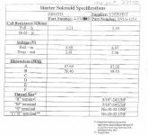
Finding detailed specs on solenoids is a bit difficult but I did find this:

1578274414050.png


1) The coil resistance is only 3.21 ohms. In the circuit, the 9 ohm precharge resistor and the coil will act as a voltage divider... when you do the math, that means the pre-charge will only go up to about 3.155 volts.... not enough to trigger the solenoid (It needs 6.69 volts). To make the circuit work reliably, the precharge resistor needs to be about 2 ohms.

2) If we change the precharge resistor to 2 ohms, the solenoid will pull in at 6.69 volts. This is lower than I would like.

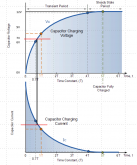
1578277559593.png

The capacitors would only be about 1/2 charged when the Solenoid trips. This is better than nothing..... but I don't think it is good enough. :( I am going to look for a better solution. Till then, the rotary switch is still best.

The only good news is that I now have some electrical characteristics of a low cost solenoid to work with.
 
The capacitors would only be about 1/2 charged when the Solenoid trips
A solenoid translates electrical energy into physical movement, are you thinking this device would move a switch to an alternative position or are you thinking of a contactor/relay where energising the coil pulls over switch contacts (...and resets them when de-energised)?

If when you say 'solenoid' you mean contactor, then you can do all the time constant tweaking you want, you're still going to have a permanently enrgised heavy duty coil. You mention the contactor you found having a coil resistance of 3R21 ohms with 6.69V required to energise it, that's a constant 2.08A (I=V/R = 6.69V / 3.21 ohms = 2.08A) load or 333Wh per day (P = VI = 6.69V x 2.08A = 13.9W x 24 hours = 333Wh). I did go and have a look for contactors on digikey, the cheapest 12VDC contactor I could find able to switch 150A or more was £74 + shipping. That one required 9V to energise and had an 11R ohms coil, or 0.818A or 177Wh per day. £74 is not cheap, and neither is 177Wh per day.

Now if when you say 'solenoid' you do actually mean a solenoid (i.e. an electromagnet used to physically move something), and that solenoid is used to turn a switch, once switched the solenoid can be de-energised - it's done its job. The way I would imagine this solution working would be:

(1) Press and hold a momentary push button until you hear a 'clunk'
(2) The button would connect the pre-charge resister to the inverter
(3) A similar circuit to that above could be used to momentarily energise the solenoid
(4) The solenoid physically rotates the switch, and is then de-energised
(5) The switch connects the battery to the inverter
(6) To isolate the inverter, physically turn the switch back
(7) Wash, rinse and repeat

Possible? Yes. Practical? No. Pragmatic? Definitely not. Just buy a £1 resister, a £15 rotary switch and suffer the 30 seconds inconvenience it takes to pre-charge manually! ;-)

Regards,
David.
 
A solenoid translates electrical energy into physical movement, are you thinking this device would move a switch to an alternative position or are you thinking of a contactor/relay where energising the coil pulls over switch contacts (...and resets them when de-energised)?

I am talking about an automotive solenoid.
1578328062963.png
I know that this is a miss-use of the term solenoid but since I am specifically talking about the low cost contactor/relay used in cars, I am using the term used in the automotive world. (Apparently the term is used in aircraft too)

If when you say 'solenoid' you mean contactor, then you can do all the time constant tweaking you want, you're still going to have a permanently enrgised heavy duty coil.
Regards,
David.

Yup.... all true. As soon as I saw that spec I realized there is a *lot* of waste in using the Solenoid/relay/contactor.

As an aside, Will often recommends bypassing the load on the BMS by using the same kind of Solenoid/relay/contactor... It will have the same waste problem

Just buy a £1 resister, a £15 rotary switch and suffer the 30 seconds inconvenience it takes to pre-charge manually! ;-)

In most of my installations, I will not be the one at the controls. Consequently, I have to worry about the end user doing it wrong. The less opportunity for it to be done wrong, the better. Unfortunately that may mean more up-front cost and it may mean a less efficient system. (An efficient system is no good if it breaks down)
  1. Right now, the best solution I have seen is the BMS that has a small timed relay that can be set up to do the pre-charge
  2. If the BMS does not have that capability, the best solution I have found is the rotary battery select switch. Even if the user rotates through quickly, they won't get the full surge. (I show a circuit for this in an earlier post.) However, the user could leave the switch in the precharge position and go away thinking the system is shut down. (I can leave a check-list.... but users have an amazing capacity for ignoring instructions)
  3. I am still trying to come up with a better but still practical solution. If I find it, I will share it.
BTW: In the diagram with the rotary switch i posted above, I show a 30 ohm resistor because that is what Will uses. However, in my installations I will be using a smaller resister, perhaps as low as 10 ohms for a 12 volt system. With 10 ohms the pre-charge would be 3 times faster but still less than 1.5 amps. This way, if the user is too quick on the rotary, they will still get a healthy amount of pre-charge as they go through the '1' position. (My SWAG is that with a 10 ohm resistor the pre-charge will be complete in about .25 seconds on a medium/small inveter)
 
However, in my installations I will be using a smaller resister, perhaps as low as 10 ohms for a 12 volt system.
Totally agree, in my tests, even milli-ohm resistances cut the current to manageable levels.

It's quite a useful circuit to re-visit time-constants, inductive load behaviour and the like. Had some fun modelling it :)

Have you every used 'everycircuit' simulator?


I was thinking of maybe using one of those solenoid-operated automatic transfer switches used to break>make grid>local off-grid supplies.

Regards,
David.
 
Totally agree, in my tests, even milli-ohm resistances cut the current to manageable levels.

I have mixed feelings about going too low.
  • In normal operation even a 10Watt resistor would barely notice the current. However, if something bad happens and the resistor is left shorted to ground, it would not handle the current. Consequently, I would like to spec the wattage high enough to handle continuous current at full voltage. That starts getting pretty big as the resistance goes down. The alternative is to put a slow blow fuse in series with it.
  • "manageable" is a relative term. As the pre-charge current goes above a few amps, I start worrying about damage to the switch.
Yes.... I worry a lot. That's what happens after you have a design that you were sure of fail spectacularly in the field. :(

It's quite a useful circuit to re-visit time-constants, inductive load behavior and the like. Had some fun modelling it :)

Have you every used 'everycircuit' simulator?

I haven't had to do an RC time calculation in 40 years (In college and exactly once after that). I had to look it up to remember how to do it. However, you are right, this nerd had fun dusting off the stuff from college.

I have never used Everycircuit. I'll have to look in to it.

I was thinking of maybe using one of those solenoid-operated automatic transfer switches used to break>make grid>local off-grid supplies.

I had not considered those.... something more to look into.
 

diy solar

diy solar
Back
Top