diy solar

diy solar

Relays

Hmmm... The Chargery BMS I am using shipped with continuous duty Normally Open contactor relays. The BMS put's out 12v/3a max for the relay switching. They are big (even for 200A) and loud when they snap closed. I did a quick search on the model and they come up on ebay etc in the $40-$60 range.

Identical to this below for a 200A (they come In 12/24/36/48 volt models.)
The PN I have for 12V 200A is MZJ-200A-D

Cheaper here on Aliexpress (not sure if same company)
Looks interesting, but no information on coil ratings. The picture indicates a dual coil which reduces consumption after contact is pulled in, which is a very good feature for BMS applications, but still not clear what holding current would be, which also depends on coil voltage.
This is obvious for experienced people, but I see some real newbies here, so to be clear you need to pick the relay with coil voltage matching your battery voltage.

@Steve_S are you able to measure holding current of your relays? Does your relay also show a picture of a dual coil L1/L2 where one coil is bypassed initially until contact is pulled in?
 
@electric
Would this work for a 12vdc or 48vdc control circuit, switching a 240v ac circuit.....i thought i needed an opto version to do that?
I'm not electrical and dont know the differences between relays, contactors and solenoids, but my aim is to have an energised 48vDC circuit control a 240v ac supply circuit such that as soon as the DC circuit is disconnected, the switch breaks the 240v ac circuit. These are two seperate circuits, with no cross over of power....only switching. Can this be done by an opto enabled version or one of the Double Pole Double Throw versions?(DC circuit on one pole and AC circuit on the other pole?)
your specific need is not the same as typical BMS disconnect, so in your case it's actually best to use AC rated SSR, attached to the heatsink.
SSR should be rated at least 2x over your actual current, so if you actually need to run 25A I would not use 25A rated SSR, I would get a 40A rated SSR or even higher.
Control side of common SSRs tops at 32V, so 48V is too high and will damage it, but since control side is very low current, you could add a series resistor to protect the control side.
However, if you are not experienced in these subjects, I would strongly advise to seek help from an experienced person. These are very high voltages on AC side and there is also a question of how many phases involved and how much heat will be created at the SSR, etc etc.
Bottom line, it is possible to do what you want, but please don't do it yourself, there is too much risk of getting hurt or causing expensive damage.
 
Do you think a RC (resistor-capacitor) would be worth trying on this set up? The idea is lower hold watts.
 
@Steve_S are you able to measure holding current of your relays? Does your relay also show a picture of a dual coil L1/L2 where one coil is bypassed initially until contact is pulled in?

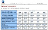
This may help answer some Q's. I am using their supplied relays, I cannot speak of others as thy vary somewhat.
RMS-Relay-info.JPG
 
Same spec’s as the China ones
I think the only way to get a lower power use relay is to go electronic vs mechanical, I looked at them and comparable DC rated ones were shockingly dear. That's a potential "upgrade" id required later, as I got the relays from Chargery with the rest, they were far less expensive than buying separately. They do not have Solid State relays on offer sadly.
 
your specific need is not the same as typical BMS disconnect, so in your case it's actually best to use AC rated SSR, attached to the heatsink.
SSR should be rated at least 2x over your actual current, so if you actually need to run 25A I would not use 25A rated SSR, I would get a 40A rated SSR or even higher.
Control side of common SSRs tops at 32V, so 48V is too high and will damage it, but since control side is very low current, you could add a series resistor to protect the control side.
However, if you are not experienced in these subjects, I would strongly advise to seek help from an experienced person. These are very high voltages on AC side and there is also a question of how many phases involved and how much heat will be created at the SSR, etc etc.
Bottom line, it is possible to do what you want, but please don't do it yourself, there is too much risk of getting hurt or causing expensive damage.
Thanks for your input electric.
 
Do you think a RC (resistor-capacitor) would be worth trying on this set up? The idea is lower hold watts.
You can't lower hold watts as it has to match with power of return spring inside the relay. If you try to reduce the current by adding a resistor, the contact will become weaker as the spring will push the contacts apart, creating hot spots, welding, etc. Really bad idea.
4 Watt hold is a really nice spec for a product in this price range and at these current ratings, why mess with it?
 

diy solar

diy solar
Back
Top