diy solar

diy solar

parallel bms?

It also seems to me that using a relay to get higher discharge amps would negate the low temp protection, since the BMS allows for discharge at low temps. The relay would therefore stay on when cold, maintaining the connection to the cells even after the BMS disallows charging through itself.

I think this is referring to the conversation in the other thread. If so, could you post the question there.
 
Filterguy, Now I'm seeing an issue with both high voltage and low voltage cutoffs. The weakest cell will trigger a bms low voltage discharge cutoff but the other bms will still allow discharge of the weakest cell for a while. Same issue with high voltage cutoff, only then the highest voltage cell will continue to charge above the cutoff value, and since the discharge/charge current would far outweigh any balancing current this could easily damage the weakest and strongest cells. Back to the drawing board. Maybe, If the bms balance voltage deadband is software adjustable above any perceived voltage discrepancy between paired cells, maybe I could parallel each pair (the +'s) as well and have both bms' charge and balance each cell pair without "fighting" each other?

1579325627909.png
 
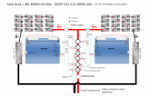
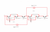
I had thought of using this set up below, thinking that no matter which parameter triggered any relay on either BMS, the central load/charge line gets disconnected.
I'm very new to this, so please point out the pitfalls in this design. Thanks


BMS double pack diagram vers 2.png
 
Hmmm, I looked at this, it just didn't seem right and it isn't. I know what your trying to do but your not actually protecting either battery in that sense. If "charge relay 1" goes off them they both packs drop, in fact any of the relays in that setup kills HOT. Instead of using 100A DC Breakers between the battery & bus, I'd suggest a MRBF 200A fuse immediately on the pack itself (I switched to using these, awfully nice)

$25 USD for the breaker & block
https://www.ebay.com/itm/Bay-Marine...hash=item2886c3133a:m:mnT1GP11ggU39co3r8gaYOQ

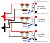
A quick doodle as I am setting things up to keep each pack happy & safe by using a common bus topology. I do not / will not use an external charger for the battery packs, their charging will be from the SCC & the Samlex Inverter / Charger, so everything goes back & forth on the 4/0 wires. Sorry about my doodle (work in progress) as I document everything when I'm done with the actual build, till then things have a way of "adapting" as things pop up. This doesn't show the finer details but rather it shows putting the packs "behind the bus" so if one pack goes to an error state, it is disconnected from the rest in the parallel bank so they are not affected. The problem with this, is the charging issue for example, if one pack is off for some reason (cold temp or LVD) hot to get it to come back & get charged (manual intervention @ remote but automated I'm not sure how/if that can be sorted. TBH I haven't spent much time pondering that particularly, yet. Although I can leverage the BMS with using ModBus via the RS232 port and program a various set of rules to manage the BMS and the interactions, so that's the work around I had figured on.
LFP-Parallel packs.jpg

A VERY IMPORTANT NOTE !

Be very aware of voltage drops ! Measure you battery packs voltage @ the terminals. Then, again measure at the "Bus Bar" and then again at the Inverter & at the SCC, write these down. You'll see the voltages are different at each point. NB Do this without ANY AC load going out but Inverter ON, then again with an average "constant" AC load being put out. Then calibrate your SCC & Inverter/Charger to correct for any line drop. Remember with LFP even a 1/2 volt miscalculation can be a potential problem, they are more finickity than FLA / AGM. For example, I have a 0.4V difference from my battery bank to my SCC and a .5 difference between the bank & inverter (even with 4/0 wire) but there are shunts, a switch in between, which all affect the end delivery voltage. Now add in relays etc into the mix and there is more points of contact which do affect the voltages. ALSO … the BMS has to reflect it's side of the equation properly too, reading it's shunt and internal circuitry, which should be independent of what the other packs are doing..

Hope that helps.
Steve
 
Thanks steve. My thinking was that no matter the parameter trigger, the whole battery bank gets shut down....everything safe first. Then the 100A(on second thoughts, this would need to be 200A) breaker could be turned off on the one pack that caused the trigger, then system powered back on, to run on the single pack for emergency use. The packs would need to be re balanced again before being coupled up again, once the fault in the defective pack was remedied.
All my workings are purely for an RV setting, so no automatic continuation of power strictly needed as such.
Problem, safety first, isolate, then repower on available pack.
 
Last edited:
Thanks steve. My thinking was that no matter the parameter trigger, the whole battery bank gets shut down....everything safe first. Then the 100A breaker could be turned off on the one pack that caused the trigger, then system powered back on, to run on the single pack for emergency use. The packs would need to be re balanced again before being coupled up again, once the fault in the defective pack was remedied.
Gee, aren't we hitting this same topic in diff places ? Maybe I need another pot of coffee ?? Ohhh the Great Java !

I see where you were thinking but as you saw in my explanation, it's not as simple "cut & dry" as it appears n the surface. With all electrical things, there is always a lurker waiting to get ya when you least expect it, your are quite aware of that obviously, but sometimes what appears to be a solution is actually a lurker waiting to wreak havoc.

The thing is, with our type of BMS' with the external relays, it provides many possibilities & lot's of flexibility to make things works in various use cases. As such that opens the door pretty wide for mistakes to be made as well, not as simple as a 2 wire BMS or a 3 wire with separate charging line. The thing is to fall back on Known Good Practices and applying the KISS principle religiously. The more complicated, the higher likelihood of a failure due to introduced weaknesses.
 
Steve,
My great disadvantage is that i have plenty of ideas, but no electrical background, so thinking from a position of ignorance. Further to this, it is all well and good to figure out something just now, but what happens in three years time if something breaks...and you have forgotten a lot of what you picked up.
I really do appreciate the amount of time you have take to explain things.
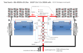
The other 'non typical' aspect, is that i wish to use an 'all in one unit' which has the charge/inverter cabling all as one(although, yours is similar idea with the one set of cables from the bus), rather than using seperate units. I've taken on board as best i can some of what you stated and amended my drawing accordingly.
Thanks Again & regards.

BMS double pack diagram vers 2.png
 
Last edited:
Steve,
My great disadvantage is that i have plenty of ideas, but no electrical background, so thinking from a position of ignorance. Further to this, it is all well and good to figure out something just now, but what happens in three years time if something breaks...and you have forgotten a lot of what you picked up.
I really do appreciate the amount of time you have take to explain things.
The other 'non typical' aspect, is that i wish to use an 'all in one unit' which has the charge/inverter cabling all as one(although, yours is similar idea with the one set of cables from the bus), rather than using seperate units. I've taken on board as best i can some of what you stated and amended my drawing accordingly.
Thanks Again & regards.

View attachment 5350
@Solarfun4jim. I think the wiring you show may not be correct. I do not have direct experience with chargery but I have read the manual (a few times). The instructions on the relay delay controller are not very clear, but he key for me was this line in the instructions:
" When large current relay closed, the small relay will be open automatically according to the below connection diagram."
I *think* this is the way it would be wired if you have an All-In-One:

1579379409835.png
Notice that the small discharge relay is not in series with the large discharge relay, instead it creates a bypass to the large discharge relay.

Note: My diagram is for a single BMS. You would put two sets of these in series for two BMSs. However, you could also rearrange the circuit to use a single discharge resistor like this:

1579381251011.png
With a couple of diodes, this can be further simplified:

1579383077132.png
Note: The flyback diode that is mentioned below would work for these diodes.

With this, the signals for the small discharge relays are "OR'd" (If either one OR the other of the signals are on, the relay turns on). (The diodes are probably not be necessary, but I would need to see the circuit of the delay board to say for sure.)

I am still pondering the best way to combine the Large Discharg relays and the Charge relays. Conceptually, 'all' you have to do is "AND" all four signals to drive one relay. If I come up with a circuit I like, I'll post it here.

One more thing: All the relays should have a flyback diode across the coil Here are some comments from Will's latest video that describes it.

Comments below suggested the use of a "Flyback Diode". Very smart idea!! This is how they work:
More information: https://en.wikipedia.org/wiki/Flyback_diode I will update my schematic for this change. Brian B put it nicely in a comment below: Great content! One way to stop shocking yourself and possibly damaging you BMS, put a large diode in the opposite direction across the coil. ie negative of the diode will go to the positive coil terminal and positive of the diode to negative terminal. This is called a 'fly back' diode. And here is another super useful comment by foxabilo:(edited) You can fit a simple diode (1N4001) pointing from the negative relay terminal to the positive relay terminal (diode band towards the positive), - ----->|----- + which will stop the shocking voltage, you can also place a suitably rated capacitor across the terminals to further dampen down fast transient voltages. (ensure it's voltage rating is higher than the maximum voltage of your system) And here is a non-sponsored link to this diode:
https://www.amazon.com/100PCS-1N4001-Rectifier-Diode-DO-204AL/dp/B07YYLQFFK/ref=sr_1_2_sspa?keywords=1N4001&qid=1579202678&sr=8-2-spons&psc=1&spLa=ZW5jcnlwdGVkUXVhbGlmaWVyPUEzSDZaS0ZEWjVFODJEJmVuY3J5cHRlZElkPUEwNDI1MDI5MkNBWjAwMlk4SUk3RSZlbmNyeXB0ZWRBZElkPUEwODIxNzY1VUxKNk9JTExGSUtOJndpZGdldE5hbWU9c3BfYXRmJmFjdGlvbj1jbGlja1JlZGlyZWN0JmRvTm90TG9nQ2xpY2s9dHJ1ZQ==
 
@Solarfun4jim. I think the wiring you show may not be correct. I do not have direct experience with chargery but I have read the manual (a few times). The instructions on the relay delay controller are not very clear, but he key for me was this line in the instructions:
" When large current relay closed, the small relay will be open automatically according to the below connection diagram."
I *think* this is the way it would be wired if you have an All-In-One:

View attachment 5356
Notice that the small discharge relay is not in series with the large discharge relay, instead it creates a bypass to the large discharge relay.

Note: My diagram is for a single BMS. You would put two sets of these in series for two BMSs. However, you could also rearrange the circuit to use a single discharge resistor like this:

View attachment 5358
With a couple of diodes, this can be further simplified:

View attachment 5360
Note: The flyback diode that is mentioned below would work for these diodes.

With this, the signals for the small discharge relays are "OR'd" (If either one OR the other of the signals are on, the relay turns on). (The diodes are probably not be necessary, but I would need to see the circuit of the delay board to say for sure.)

I am still pondering the best way to combine the Large Discharg relays and the Charge relays. Conceptually, 'all' you have to do is "AND" all four signals to drive one relay. If I come up with a circuit I like, I'll post it here.

One more thing: All the relays should have a flyback diode across the coil Here are some comments from Will's latest video that describes it.

Comments below suggested the use of a "Flyback Diode". Very smart idea!! This is how they work:
More information: https://en.wikipedia.org/wiki/Flyback_diode I will update my schematic for this change. Brian B put it nicely in a comment below: Great content! One way to stop shocking yourself and possibly damaging you BMS, put a large diode in the opposite direction across the coil. ie negative of the diode will go to the positive coil terminal and positive of the diode to negative terminal. This is called a 'fly back' diode. And here is another super useful comment by foxabilo:(edited) You can fit a simple diode (1N4001) pointing from the negative relay terminal to the positive relay terminal (diode band towards the positive), - ----->|----- + which will stop the shocking voltage, you can also place a suitably rated capacitor across the terminals to further dampen down fast transient voltages. (ensure it's voltage rating is higher than the maximum voltage of your system) And here is a non-sponsored link to this diode:
https://www.amazon.com/100PCS-1N4001-Rectifier-Diode-DO-204AL/dp/B07YYLQFFK/ref=sr_1_2_sspa?keywords=1N4001&qid=1579202678&sr=8-2-spons&psc=1&spLa=ZW5jcnlwdGVkUXVhbGlmaWVyPUEzSDZaS0ZEWjVFODJEJmVuY3J5cHRlZElkPUEwNDI1MDI5MkNBWjAwMlk4SUk3RSZlbmNyeXB0ZWRBZElkPUEwODIxNzY1VUxKNk9JTExGSUtOJndpZGdldE5hbWU9c3BfYXRmJmFjdGlvbj1jbGlja1JlZGlyZWN0JmRvTm90TG9nQ2xpY2s9dHJ1ZQ==
Copied your post to read over a few times. Thanks for the input.

re read your diagram and now realise you simply added in the rest of the load circuit from the large discharge relay....gotcha now.
 
Last edited:
Filterguy, i think for the way i'd want to use it, i would need to incorporate a couple of bypass switches, so that i could activate one pack after a shutdown....along these lines...simply close one for whichever pack is needed, after the trigger event.

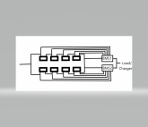
Dual bms layout with bypasses.png
 
I am still pondering the best way to combine the Large Discharg relays and the Charge relays. Conceptually, 'all' you have to do is "AND" all four signals to drive one relay. If I come up with a circuit I like, I'll post it here.

OK, The two Charge relays and the two Large Current Discharge relays create a logical AND. (All of them must be on for the current to flow).

The problem with this is that you have 4 relays in the circuit, Each creating a voltage drop and each drawing a lot of current.

I am not real happy with it but the following circuit uses 4 small relays for the logic, and then feeds the result into a single power relay.

1579392232477.png
Notes:
  • You could use this for the 4 small relays: https://www.amazon.com/Electronics-Salon-Mount-Interface-Module-Version/dp/B00M1MZN4I/
    You could use this to mount the above relay module: https://www.amazon.com/Piece-Slotted-Aluminum-Inches-7-5mm/dp/B01FT485S0
  • The Main Relay coil should be the same voltage as the system voltage. (I think the Chargery uses 12V relays even on 24V systems)
  • The diagram above includes the flyback diodes on the power relays. I believe the small relay module I reference has the fly-back diodes built in.
  • One difference of this circuit is that If one BMS tries to turn on discharge while the other is off, the low-current discharge will happen for the timed amount.... but this should not be a problem.
  • The Chargery manual does not show fuses on the outputs of the relay delay control board, so I don't show fuses here. However, if one of the coil circuits shorts, the likely result would be a burnt out delay board or a lot of smoke. You might consider fusing each output of the delay board.
What I like about this:
  1. There is an automated low-current discharge circuit that will pre-charge the inverter capacitors and eliminate the inrush current.
  2. There is only one relay in the primary circuit path
    * Lower voltage drop
    * Fewer high cost relays
  3. The power to drive the 4 smaller relays and one power relay is considerably less than if you drove 4 power relays.
What I don't like about this.
  1. Does the circuitry reduce or improve the reliability of the overall system?
  2. There is still a power relay drawing current whenever the power is on.
  3. It feels more complicated than it needs to be.
If I think of a better circuit I will let you know.
 
Last edited:
Filterguy, i think for the way i'd want to use it, i would need to incorporate a couple of bypass switches, so that i could activate one pack after a shutdown....along these lines...simply close one for whichever pack is needed, after the trigger event.

View attachment 5368
Yes. Make sure you use a quality high current bypass switch. I would look for a battery disconnect switch.
 
Here it is with bypass switches.

View attachment 5369

The bypass switches can be lower current toggle switches.
I would love it if you could attach some quality UK supply URLs to these items/relays/switchgear(as you will know far better what is good), ie like perhaps using these for the bypass switches???
 
Here it is with bypass switches.

View attachment 5369

The bypass switches can be lower current toggle switches.
Thinking out loud, if you had a trigger event, bypassed the defective pack and ran the good one down, repaired the defective pack, then seperately charge each pack back up to the same full soc voltage(seperately) before bringing them back into parallel again, would this help maintain the top balance aspect?
 
I would love it if you could attach some quality UK supply URLs to these items/relays/switchgear(as you will know far better what is good), ie like perhaps using these for the bypass switches???
[/QUOTE
I don't have experience with that particular switch, but it looks reasonable (On a 48 volt I assume your normal load is 100A or less???)

BTW: It would be best to only change those switches when both BMSs are off. This would prevent any arcing/pitting due to surge currents.


As I was looking for a UK link to the 4 channel relay module, I realized the one I pointed to may not work for you.r 48 volt system (It needs a 12 volt supply voltage).... I'll see if I can find a good replacement. The options drop off quickly with 48 volt.
 
Thanks filterguy, much appreciated.
Yes the max continuous load would be 100A with a 200A peak surge.
Either bypass switch would only be closed after a triggered event, in which the BMS's would both be at off. Once the bypass on good pack was closed, simply activate the switch on the delay relay board....at least that was my thinking??
 
Thinking out loud, if you had a trigger event, bypassed the defective pack and ran the good one down, repaired the defective pack, then seperately charge each pack back up to the same full soc voltage(seperately) before bringing them back into parallel again, would this help maintain the top balance aspect?

Yes. THat is a very good point. You don't want to reconnect them if the voltage is too far out of whack. However, the charge curve is so flat it is really only a problem if one of the batteries is fully charged and the other is not. If they are both on the 'Flat' of the voltage-charge curve, you are probably ok to put them together.
 
Yes. THat is a very good point. You don't want to reconnect them if the voltage is too far out of whack. However, the charge curve is so flat it is really only a problem if one of the batteries is fully charged and the other is not. If they are both on the 'Flat' of the voltage-charge curve, you are probably ok to put them together.
Correction:

However, the charge curve is so flat it is really only a problem if one of the batteries is fully charged or fully discharged and the other is not.
 
Filterguy, in your drawing, i note that your two bms small discharge relay outputs are connected in parallel to the one coil. Excuse my ignorance, but how exactly does that impact the spec of the relay needed?
 
@Solarfun4jim: You drew out a 16S2P arrangement for your batteries. Is there a reason you arn't doing a 2P16S arrangement?

1579399195337.png

This would allow you to use 1 BMS and therefor greatly simplify things.

There are two downsides of 2P16S that I can think of:

1) You lose the ability to have half your system still working in an error condition.
2) It would be slightly harder to detect a cell that went bad.

I am not sure what your use case and priorities are, but I would personally go with 2P16S
 
Filterguy, in your drawing, i note that your two bms small discharge relay outputs are connected in parallel to the one coil. Excuse my ignorance, but how exactly does that impact the spec of the relay needed?
It doesn't. If either BMS supplies 12 volts, the relay sees 12 volts. If Both BMSs supply 12 volts, it still only sees 12 volts.
 
@Solarfun4jim: You drew out a 16S2P arrangement for your batteries. Is there a reason you arn't doing a 2P16S arrangement?

View attachment 5370

This would allow you to use 1 BMS and therefor greatly simplify things.

There are two downsides of 2P16S that I can think of:

1) You lose the ability to have half your system still working in an error condition.
2) It would be slightly harder to detect a cell that went bad.

I am not sure what your use case and priorities are, but I would personally go with 2P16S
I felt it was more important to monitor every single cell. I was also looking to add in an active balancer on every cell, thus maintaining balance on both the way up and down. Moving 6A about between cells actively is going to be far better than 1.2A passively, when it comes to a large bank...or so my thinking goes???
 

diy solar

diy solar
Back
Top