


You are using an out of date browser. It may not display this or other websites correctly.
You should upgrade or use an alternative browser.
You should upgrade or use an alternative browser.
Ryobi Zero-Turn Mower SLA to LiFePo4 Conversion - (Updated - Build Complete With Pics!)
- Thread starter AMDPower
- Start date

rio
New Member
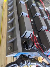
That looks really clean!
Yes, PLA 30% infill. Heat isn't going to be a problem. Probably would do PETG for a bit strong material, but not really concerned as I don't have huge holes in the yard.Looks really nice! Did you say what you used? Is it PLA?
rio
New Member
Just found these two 48V chargers by EG4. https://shop.signaturesolar.us/collections/48v-battery-chargers
Both have a 5yr warranty. I just wish they had a 10A version at an in-between price! But maybe the 5A version would be just fine... If we're now getting enough range to comfortably finish the job in one shot then probably no big deal if it takes 15+ hours to recharge. What do you guys think?
Both have a 5yr warranty. I just wish they had a 10A version at an in-between price! But maybe the 5A version would be just fine... If we're now getting enough range to comfortably finish the job in one shot then probably no big deal if it takes 15+ hours to recharge. What do you guys think?
Awesome! Wished there was a 10A version as well. Also curious if the voltage could be adjusted down like the one from Amazon?I'd definitely go for that 5A. I just cut my grass again and it wasn't wet and didn't need to go over it twice. 70% remaining after I cut!
Did you guys see this? Possible drop in replacement. $1650 before shipping/taxes though.
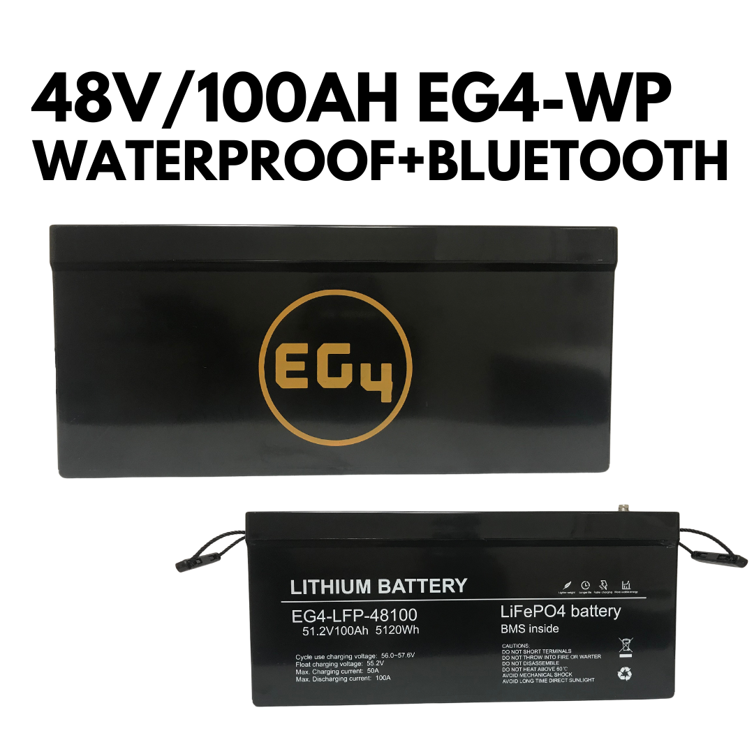
48V 100AH Water-Proof Bluetooth Battery by EG4
ADD-ON CHARGER DEAL Get the EG4 LiFePo4 Battery Charger for 33% off in cart DESCRIPTION SPECS & MANUAL VIDEOS SHIPPING 48V 100Ah EG4-WP Waterproof LiFePo4 5.12kWh Lithium Battery with Bluetooth Monitoring and Built-In BMS 20.5L x 10.5W x 9.125H This battery is the ULTIMATE upgrade to any...
shop.signaturesolar.us
rio
New Member
I called them and they said it is not adjustable. From everything I've found, it seems that the standard LiFePO4 charger is set for a max voltage of 3.6 or 3.65V per cell. Adjustability does not seem to be a common parameter, which makes me wonder if I'm asking the wrong questions. And now the one you guys got from Amazon is out of stock. I may post a battery charge question in the DIY LifePO4 Battery Banks section of this forum. I guess my biggest misunderstanding is that I thought the consensus is not to charge routinely to 100% SoC if not necessary (rather, to 80 or 90%). From what @AMDPower said, it sounds like the folks at Overkill are suggesting that the BMS should not be used for limiting charge voltage. I'm guessing that in the DIY solar world this is somewhat moot since they're not charging their batteries from an outlet.Awesome! Wished there was a 10A version as well. Also curious if the voltage could be adjusted down like the one from Amazon?
I got my batteries and should have my BMS tomorrow. Now I'm planning on how to top-balance. The batteries were shipped at approx. 40% SOC. I have access to a power supply that can put out 50+ volts with a 3A limit, and under 5V with a 6A limit. Putting them in parallel at 6A would take forever (6/16 = 0.375A per cell -- 160 hours to reach 100%!). So I'm thinking about hooking them up in series with the BMS and charging them to about 56-57V (3A limit) first, which should take about 20 hours, and then switch them to parallel for the last little bit up to 3.65V. How did you guys handle this?
rio
New Member
Wow, I must admit I would have been very tempted if I saw it before purchasing my cells. But the money saved plus the learning experience is totally worth it.Did you guys see this? Possible drop in replacement. $1650 before shipping/taxes though.
AMDPower
New Member
- Joined
- May 18, 2021
- Messages
- 123
@rio Don't charge at that higher voltage. Just parallel and charge at 3.65v @ 6A. That was a mistake I made. My cells are pretty perfectly balanced now but it took a while. Would have saved a ton of time if I did it right. Also to clarify, my cells still charge to 100% at 56V. But I don't get any cell overvoltage errors and it's a slower charge. To charge to sub-100%, I just disconnect when I reach that capacity. If I wanted to charge down to 80% I'd probably need to charge at 54.5 or something. A lot of this was due to me not top balancing correctly in the first place by the way. But also, the power supply was outputting a bit hot. Just make sure you do everything correctly from the get go and you should be good. Also, I bet the power supply IS adjustable but they probably don't support it. But who knows for sure. I'd look around and see if anybody has tweaked it.
rio
New Member
I thought your situation was different in that you just never top-balanced them in parallel. The procedures outlined by Will Prowse and Filter Guy both recommend to pre-charge them in series (if SoC is not already close to 100%) as long as it is followed by a parallel top-balance. So I will definitely be charging them in parallel to top-balance. Attached is the procedure written by Filter Guy. Please let me know if you think I'm missing something!
You're probably right about the PS adjustability. I'm definitely leaning towards the EG4. I also just found somewhere and endorsement by Will Prowse on this very charger. If the charger does no turn off automatically after topping out I may add an outlet timer or something like that.
You're probably right about the PS adjustability. I'm definitely leaning towards the EG4. I also just found somewhere and endorsement by Will Prowse on this very charger. If the charger does no turn off automatically after topping out I may add an outlet timer or something like that.
Attachments
Hedges
I See Electromagnetic Fields!
- Joined
- Mar 28, 2020
- Messages
- 21,840
As instructions say, use BMS when charging in series.
If you have a small charger, current is already low, so slowly charging to 3.65V/cell reaches higher SoC than fast charging and tapering. You might want to terminate at a lower voltage. Maybe program BMS for lower cell voltage disconnect for this step.
Having assembled the pack, you might not want to disassemble. You can top off each cell individually with CV/CC charger.
In that case, perhaps BMS can also monitor cell voltage for you (given suitable max cell voltage and max imbalance between cells.) If it disconnects 48V output, that could control a relay to shut off AC to charger.
If your non-adjustable charger is higher voltage than you like (might trigger BMS every charge cycle), possibly you can drop voltage by putting through some diodes. But I'm not sure, because with their exponential current/voltage curve, at low (near zero) current, voltage drop is reduced.
rio
New Member
Thanks @Hedges. Yes, I will use the BMS for this step. I will do this on a bench top so not worried about assembly/disassembly (considering the ~160 hours it would take to set them up in parallel at their current 40% SOC).
Very interesting idea!
In that case, perhaps BMS can also monitor cell voltage for you (given suitable max cell voltage and max imbalance between cells.) If it disconnects 48V output, that could control a relay to shut off AC to charger.
Very interesting idea!
rio
New Member
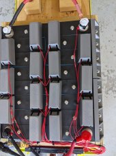
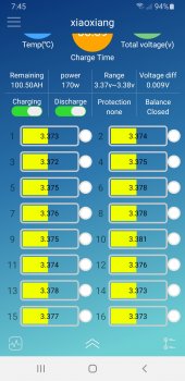
Cells have been slowly charging at 3A in series for about 20 hours now. The Overkill app estimates that they are at full SoC (based on current over time), but the cells voltages are still lagging. Based on the charge voltage curves, I expect these numbers will start rising sharply very soon. Once any cell gets to 3.55 I will put them in parallel and top balance.
I heard back from Overkill about using the overvoltage protection setting as a means to control the upper charge voltage. He said that while it is not ideal, it will work just fine. So if my charger voltage cannot be adjusted down from 58.4V, then my plan is to just set my overvoltage protection at 54V or so, with a much lower release so that it doesn't cycle back and forth.
Still looking around for a charger. I found this one that I like: AIMS 48V Charger, but at 19A it might be too much for the charge lines in the Ryobi, which are all 14 AWG. I may just resort to the 5A charger from EG4.
Hope to have this done by next weekend if life doesn't get in the way...
Attachments
Nice! I also charged in series until first cell was over 3.5V then placed all cells in parallel and put on bench PSU set to 3.7 and left them for a few hours until amperage was down to ~0. I then disconnected the PSU and left the cells overnight connected in parallel. The next day I reconnected the cells in series.Cells have been slowly charging at 3A in series for about 20 hours now. The Overkill app estimates that they are at full SoC (based on current over time), but the cells voltages are still lagging. Based on the charge voltage curves, I expect these numbers will start rising sharply very soon. Once any cell gets to 3.55 I will put them in parallel and top balance.
I heard back from Overkill about using the overvoltage protection setting as a means to control the upper charge voltage. He said that while it is not ideal, it will work just fine. So if my charger voltage cannot be adjusted down from 58.4V, then my plan is to just set my overvoltage protection at 54V or so, with a much lower release so that it doesn't cycle back and forth.
Still looking around for a charger. I found this one that I like: AIMS 48V Charger, but at 19A it might be too much for the charge lines in the Ryobi, which are all 14 AWG. I may just resort to the 5A charger from EG4.
Hope to have this done by next weekend if life doesn't get in the way...
So the charger does seem to work and I've added a wifi switch. However, I still disconnect it because the batteries seem to keep the charger powered up. There is also arcing that occurs when connecting the charger... not cool.
I found a better charger from AIMS, but it's pricey at $275-$300 so I haven't purchased it yet. Here's a spec sheet: https://www.aimscorp.net/documents/CON120AC3648VDC.pdf
Out of the box it seems to have the voltages that I would like with proper lower voltage float so this could remain connected 24/7 as long as your BMS has low temp cutoff(which mine does not have).
Current connected sell them here: https://www.currentconnected.com/product/aims-con/
rio
New Member
Yeah that's the same charger from my link above. My concern is that at 19A, I'm not sure if I would want to to rig it to plug into the Ryobi charger port, since that is all 14AWG and designed for the 13A Delta charger. So then an alternative could be to wire it into an Anderson-style plug that matches the main power disconnect under the seat, and just forget about using the charge port altogether. Then to charge one would pop the seat up, disconnect the main power plug, and connect the charger instead.
That all said, 19A is probably fine for the existing charger port but it's at the very high end of 14AWG ampacity. Just something that would keep me wondering.
That all said, 19A is probably fine for the existing charger port but it's at the very high end of 14AWG ampacity. Just something that would keep me wondering.
Last edited:
AMDPower
New Member
- Joined
- May 18, 2021
- Messages
- 123
That arcing is definitely not cool. Was throwing my GFCI every time if I forgot to power it "off" first. Since I've already got my Raspberry Pi connected for monitoring, I think I'm going to automate a turn off of the WIFI switch when I reach 80% and turn back on when it goes below some other percentage.
Hedges
I See Electromagnetic Fields!
- Joined
- Mar 28, 2020
- Messages
- 21,840
Here's a possible "Danger Zone!" solution - try putting a common-mode choke in the charger power cord. One coil for each of Line, Neutral.
This is a 2-winding common mode choke, but needs to be low-frequency, not some 1 MHz and up EMI filter. This could even be two identical windings of a transformer (so long as rated for the current your charger draws.) For instance, I got a transformer with 120V primary, dual 9V secondary. Capped the 120V leads, used the two secondary coils as a 2-winding common-mode choke for 208VAC.
The choke allows current out Line only if equal current back through Neutral, actually sucks balanced current back through neutral, to prevent it from partially going through ground.
Actually, not sure any danger to this solution, but I make no guarantees. I'm messing with some related applications where I need to be more careful.
AMDPower
New Member
- Joined
- May 18, 2021
- Messages
- 123
So... Would I be able to get this charge controller and 4 12v panels in series and hook it right up my charger cable? I'm wondering if it would be this easy charge my mower with solar.
Similar threads
- Replies
- 3
- Views
- 369
- Replies
- 16
- Views
- 399
- Replies
- 7
- Views
- 863
- Replies
- 2
- Views
- 289