diy solar

diy solar

DIY 280Amp LifePo4 With BMS voltage problem.

larrylwill

New Member
Joined
Aug 22, 2021
Messages
92
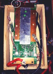
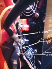
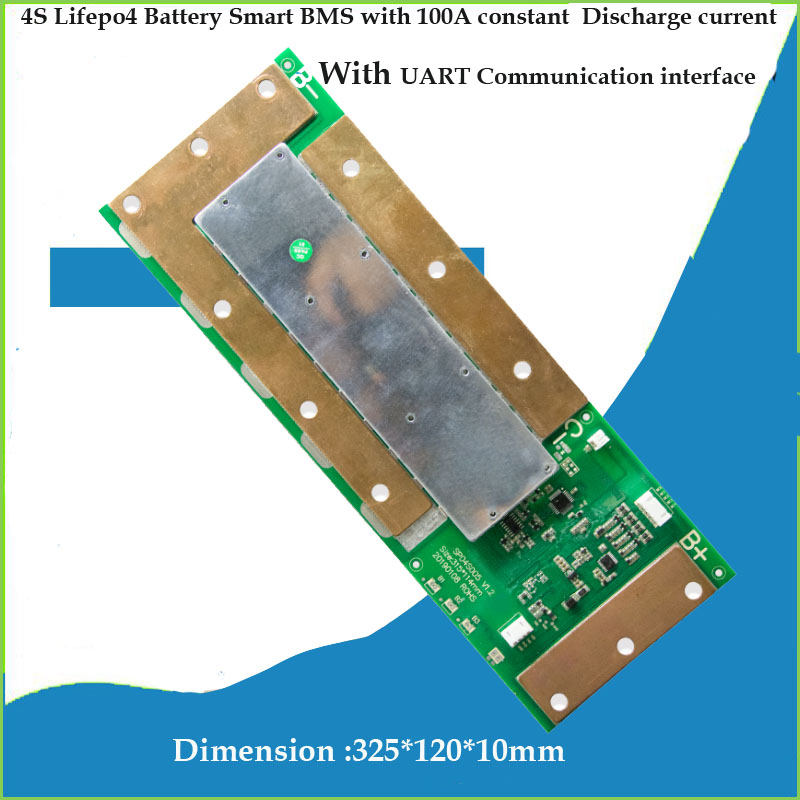
I built a 280Amp LifePo4 pack with Xiaoxiang 150 Amp BMS recently, I added a Inverter, charger, AC switch and installed it in my motorhome. Everything is hooked up correct and working. After a few weeks I found that I have a 0.5amp drain on the battery. Today I was trying to find the phantom load and disconnected the Neg B- battery wire. Only the B+ and C- wires still connected but the 12v system was still active. I found that if I disconnected the Balance wires the battery was no longer connected. So somehow the balance wires are feeding the 12v to the load. Is it possible that one or more of the balance circuits is bad? Right now I only have the B-. C- and balance wires connected. All readings with an ohm meter and the app are correct and everything seems to be working except for this problem. Anything I'm overlooking? I haven't found the 0.5 amp drain yet.
Ha1be8e9813a0447396fb7fadefe7be876.jpg
 
Last edited:
If you disconnect the balance wires, the BMS will cut power as it cannot read the cell voltages.
Best to use a DC clamp-on ammeter to find the 500 milliamp draw.
That draw is fairly normal for an RV to power electronic controls, radio memory, detectors, etc.
 
I understand but I disconnected the Neg battery wire from the RV, The power has to be coming through the balance wires. There is nothing running especially when I have a DC cut off switch to disconnect the battery when plugged in. I have a clamp on Ammeter but I want to find out why I have house battery power unless I remove balance wires first. I will work on it today.
 
I understand but I disconnected the Neg battery wire from the RV, The power has to be coming through the balance wires. There is nothing running especially when I have a DC cut off switch to disconnect the battery when plugged in. I have a clamp on Ammeter but I want to find out why I have house battery power unless I remove balance wires first. I will work on it today.
Please post a picture
 
Pictures
 

Attachments

  • 20211125_161333.jpg
    20211125_161333.jpg
    199.6 KB · Views: 31
  • 20211125_161558.jpg
    20211125_161558.jpg
    717 KB · Views: 30
Are you seeing the 0.5A as reported by the BMS? I have the same BMS (2x 150A version) on two 280Ah battery packs. My BMS reports about 1.5-1.8A draw overnight (no solar to cover it) but I have two BMS plus the RV DC loads including a wifi router and inverter (connected but not turned on in standby). If I recall it showed 0A draw when it was just the BMS & cells connected with nothing tied to them.

I also only have a small connection to the B+ on the BMS as I understood it was only needed to support the heaters load. Some docs show nothing connected to it and let the BMS power itself thru the balance wires 12v connection.
 
Where do you have your battery Pos and Neg connected? (also only have a small connection to the B+ on the BMS) Since the load is on the C- all the battery current to the system has to come from the B+ of the battery to the BMS so a small wire should get hot.

The 0.5A is read on my Trimetric battery monitor, Its a shunt on the Neg wire to the chassis. Its very accurate. Besides the battery goes from 100% to 60% in about 3 weeks. Some could be the readout of the monitor itself.
I have only the battery neg on the B- and only the Battery Pos on the B+ connector. I have the battery circuit disconnected at the MH service panel. I can turn it on or off so It cant be the Propane monitor its turned off also the Trimetric. It could be the Inverter even though its turned off. The 0.5a only shows up when the MH is powered which could be the Propane monitor and Trimetric leds, but when turned off the battery on my panel those are turned off. I keep the MH in my garage plugged in. What does your battery read after a couple weeks.
Im also having strangest with cell 2. When I got them it was low, about 130mv after balance it was ok, then it started reading higher then the rest, now its back to reading low. I find the app is not that accurate, Im using the CarploungeBMS app. Right now it reads 3.569, 3.508, 3.558 and 3.565
 
@larrylwill
In the photo of your board in post #7, it appears that you might be using all of the balance leads. The two wiring method diagrams in Post #1 do not show all five of the balance leads being used.

In method #2, where they have no connection to B+, they are using the red and three white balance leads, but not the black. I found a similar diagram on the lithiumbatterypcb.com website. If you scroll down to the diagram, it specifically states not to attach the bc0 balance lead.

In method #1, where there is a connection to both B+ and B-, they show only three balance leads in use. but they show them connected to pads on the other side of the board. There are traces from those pads over to the balance lead connector, so I believe that those are the three white wires on the balance connector, which makes sense since they are called bc1, bc2, and bc3.

So what I concluded from looking at the diagrams is that the red balance lead has a direct connection to the B+ pad and the black balance lead has a direct connection to the B- pad. If you are using the black balance lead, this would be why you still had power with the B- pad disconnected.

They appear to be using the B- current carrying conductor as part of the balance/cell voltage detection circuit. This is a poor design for accuracy, as the voltage drop in the current carrying wire will affect voltage detection. For this reason, I think this is a not a good quality BMS.
 
hankcurt: Good catch. I looked at the diagram 100 times and never noticed what you saw. It came with no instructions, so I just connected it as in diagram 1 and hooked up all the balance wires. +, - and each cell. I think what you observed is correct. In your opinion which method would be the best. Thanks
 
Since the BMS really only controls the connection between the B- and C- connections, and does not act on the current at the B+ pad, I would say that the best option is to use the red balance wire and not connect anything to the B+ pad. The advantage of not using the B+ pad is that voltage drop on the positive power cable won't interfere with voltage sensing on the positive most cell.

You still have to not use the black balance wire and just keep the connection between the battery and the B- pad as short and as low resistance as possible. Voltage drop on that power cable will affect the voltage reading on the most negative cell.
 
So I think your saying is connect the battery to the inverter and leave out the BMS, also remove the Black balance wire.
 
So I think your saying is connect the battery to the inverter and leave out the BMS, also remove the Black balance wire.
I'm not using the black balance wire in my setup. I assume you mean to not use the B+ as a junction point.

If at some point you use the onboard heater controls you'll want a power feed back to the B+
 
Yes, I would connect the positive battery cable to the load/charging device directly.

Also, once you are no longer using the black balance wire, I would be very cautious about removing the connection to B-. The installation instructions say to connect B- before connecting the balance leads. They don't say what bad thing happens if you don't connect B-.
Any time I'm disconnecting the BMS from the battery I pull the balance connector first. I also connect it last when putting it together.

I built my batteries as standalone packs. They connect to bus bars before connecting to loads. The connection to the inverter should have a suitable fuse inline
 
1637956489423.jpeg

Is the the current BMS wiring?
Pin 1 of the balance lead needs to go to negative terminal in lower right (cell #1). Pin 2 to positive on cell1. Pin 3 to positive on cell 2. Pin 4 to positive on cell 4.
 
View attachment 73588

Is the the current BMS wiring?
Pin 1 of the balance lead needs to go to negative terminal in lower right (cell #1). Pin 2 to positive on cell1. Pin 3 to positive on cell 2. Pin 4 to positive on cell 4.
Yes, that's essentially a current picture but no, the negative lead (black)in the balance wire connector is not required to be connected to the batteries. That connection is already made by the B- on the BMS. Some drawings show it connected, some don't. I chose to not connect it and the pack is running fine.

 
Last edited:
Well after making the changes I hooked up a 1500w heater to my 2000w inverter which works fine. Then I turned on the Voltstart, which starts the engine if the voltage of the house battery gets too low and the battery is charged from the High amp alternator. I just found out that it puts out 280Amps, the BMS is 150A, so after a minuet or so it shuts down. After another minute it restarts and so on. So what to do. What do you think? any solutions other than a 200A BMS?
 
Last edited:
There are some potential problems (such as frying your alternator) when charging LiFePo4 batteries from a vehicle charging system. I don't have any first hand knowledge of the best methods of dealing with this, so someone else would be a better source of information.

The basic problem seems to be that the charging systems were designed with lead acid in mind, and that chemistry has a relatively high internal resistance compared to lithium, so if the charging system relies on the battery internal resistance to limit current, stuff might burn out when charging lithium batteries. You may want to look at this thread - https://diysolarforum.com/threads/lifepo4-and-auto-alternator-concerns.9521/
 
How many charge amps does the BMS show when it shuts down? I charged my batteries this afternoon from the onboard Progressive Dynamics unit which is capable of 90A. The batteries were @ 80% and after a minute or two @ 60A they dropped to taking ~42A total (21A each).

You could use a DC to DC unit which is designed to isolate the alternator from the batteries and conform to the Li charge profile. Depending on the vehicle the onboard alternator can charge at >15v which isn't good for Li. Renogy and others make the units
 
Before I pulled the battery down with the 1500w heater It would charge the battery full without problems, but when the battery got low and the heater was running the current increased to about 180A, on my app, when the BMS shut down it dropped to 0A then back up to 180A, If I allowed it to cycle I'm sure it would eventually get lower than 180A but I don't think letting the BMS cycle is a good Idea, I don't know.
 
Before I pulled the battery down with the 1500w heater It would charge the battery full without problems, but when the battery got low and the heater was running the current increased to about 180A, on my app, when the BMS shut down it dropped to 0A then back up to 180A, If I allowed it to cycle I'm sure it would eventually get lower than 180A but I don't think letting the BMS cycle is a good Idea, I don't know.
No, not good to let the BMS act as the disconnect. You need to have equipment between the alternator and the BMS to control the charge current.

Like this: https://www.renogy.com/12v-60a-dc-to-dc-battery-charger/

BTW, I just disconnected the shore power from my trailer and the 12v draw dropped to 0.1-0.2A from almost 2A. I had the fridge running on AC power but it obviously draws some DC too for the controller.
 

diy solar

diy solar
Back
Top