diy solar

diy solar

3P, 4S vs 4S, 3P with a single BMS?

Right, but that imbalance in currents can be created in more than one way. Instead of a high impedance cell, for example, imagine that all the cells are exactly matched but the connection between one cell and its busbar has some resistance. In that case, that same "sideways" current would flow.
No. You will simply end with three 315Ah cell with low impedance and one almost 315Ah cell with higher impedance.

It's easier to have a good connection between busbar and cells terminals than between cell terminal lug, wire, lug and cell terminal.
 
No. You will simply end with three 315Ah cell with low impedance and one almost 315Ah cell with higher impedance.

It's easier to have a good connection between busbar and cells terminals than between cell terminal lug, wire, lug and cell terminal.
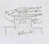
Well, yes, there are more parts involved when the wiring terminal is inserted in there. But the thing is that I'm seeing several mv between the screw that holds everything together and the busbar that sits directly under it, and essentially no drop between the screw head and the terminal itself (if I angle my meter probe to hit the terminal without touching the busbar). This is true for even those connections where only a busbar is involved (no wiring). Each battery terminal seems a little different, though I can't tell if that's because of the connections or the relative currents due to balance. Basically, the screw is making good electrical contact with the terminal its screwed into, but the busbar may not be. Everything is tight.

There is no voltage drop between the busbar and the wiring's terminal, on those connections that host the cross-connects, so the side-to-side wiring is being called upon to carry a current that should have been directed to the attached cells instead. I need to fix that connection first. I don't see how a traditional busbars-only configuration would fare any better, given the odd electrical connections I'm seeing.
 

Attachments

  • battery connection issue.jpg
    battery connection issue.jpg
    20.2 KB · Views: 8
Last edited:
The only voltage drop you need worry about is between the terminal and the bus bar.
No current should be flowing through the bolt.
 
The only voltage drop you need worry about is between the terminal and the bus bar.
No current should be flowing through the bolt.
Essentially true, hence my conclusion that the busbar to terminal connection isn't working properly.

Actually, the connection between the terminal and the bottom of the busbar is in parallel with the connection between the top of the busbar and the bolt head, so some current will flow through the bolt's shaft. But it should be minimal if the bottom contact is robust; there's considerably more contact area on the bottom so the lower resistance there will pick up the bulk of the current. It's an easy thing to measure the voltage between the bolt top and busbar; highly recommended as a verification that all is well. If you get a reading other than zero (or very close to it) it's time for some troubleshooting.

So an update from last night: I bought a bunch of copper washers at the local hardware store, and got a few installed between the terminal and bottom of the busbars as a test. They seem to improve that connection substantially! Voltage drop between the terminal and busbar is measuring between zero and perhaps a fraction of a mv. I need to get a few more and finish the upgrade across the entire battery. Some of the bolts are a bit short for the task, so they will be upgraded too.

Not much sun today for the solar panels, and a yet another storm on the way, so it will be a few days before I can report back on how the full pack behaves with a higher current flow. I should probably also do another active top balance with the iCharger, just in case the bad connections had an adverse effect since the pack was initially set up.
 
Closing this out... I've added a copper washer between each cell terminal and the busbar above. The three terminals in the middle stack that had both a busbar and three lugs on top (left and right balance wires, plus the BMS sense wire) got new longer bolts in order to assure enough "bite" into the cells.

I'm getting about 5 amps charging from the Sun right now between clouds, about what some of the troubleshooting was done at before, but cannot find any point that is more than 0.9mv different going side-to-side across the stacks, including across the balance wires. Most are under 0.5mv. This is a massive improvement, confirming to me that the "balance" currents seen earlier were actually a result of the poor connections to the terminals, not due to the overall design of the battery or an imbalance among the cells. The BMS is still reporting an 8mv top to bottom balance differential.

Calling it done. Thanks for the help and support.
 
Last edited:
Back
Top