diy solar

diy solar

Using solar micro inverters with batteries instead of panels

I hook the Iq7x directly to the battery bank. So no Buck Converter is used in my setup....not sure for what reason you would need one? (to raise the voltage?)

It always pulled 6 amps when it was inverting. I run to a high voltage of almost 70 volts and it stayed at 6 amps all the time above 33 volts. 6 amps is 6 amps so the battery can't push more then that.

Good Luck with your project, are you going to try the M215-60-230-S22 in this way....It was easy to test, I used a Victron Smart Shunt to do all my measurements on the DC side.
 
Last edited:
Again...Thanks very much.
Yes I have 2 x 24 Volt Systems. So I need to raise the voltage for one system.
The buck converter I have ordered should do the trick. It can take up to 15 Amps.
It has good range on the input side (10V ~ 60V) and the output side (12V ~ 80V). 95% efficiency.

Yes M215-60-230-S22. But I also have an IQ7.

I have a shunt connected. I use a local shunt made by EV Power. (Western Australia).
Their BMS is very neat https://www.ev-power.com.au/lithium-bms/

I will let know how I get on. The Buck Converters arrive 13 Dec 2021.
 
I wouldn't do it! (but I think there is a solution...)
In the best case, the MPPT algorithm of the microinverter would never lock, and output would fluctuate.
In the worst case it would simply fry your microinverter and/or ruin your batteries.

There are some grid-tie inverters that are actually designed for this (like the SUN 2000W) , but I don't know of any microinverters that have this feature.

What the MPPT algorithm is looking for is a maximum power point. With batteries, the maximum power point is theoretically infinite.

But, maybe you can use one if these DC-DC boost converters in betweenyour batteries and the microinverter, which has a current limiting function.
For example, lets say you set your DC-DC converter to a maximum of 15 amps and 36v. If the microinverter will try to pull more than 15amps, the DC-DC will lower the voltage accordingly. The MPPT should then understand that it went too far with the current and slowly bring it down.

All this is in theory, I haven't tried it, but I did play with some of these DC-DC boost converters. They are pretty nice and cheap, but a bit if a pain to setup (using pots to set voltage and maximum current).

I would suggest you get one and experiment slowly. I would set the maximum voltage a bit less than your microinverter's maximum voltage, and the amps at almost the maximum the microinverters can handle.
But make sure that this is inline with your batteries abilities and your wiring guage.
If you set it properly, it should protect your batteries a bit, but still I would add proper fusing just in case.

There are different versions of these cheap DC-DC boost converters, but I would get the 1800w one, just because it has a temperature controlled fan, and its beefier.
These guys generate heat at high loads, so make sure to keep them indoors and properly ventilated.


Good luck... and stay safe.
 
I wouldn't do it! (but I think there is a solution...)
In the best case, the MPPT algorithm of the microinverter would never lock, and output would fluctuate.
In the worst case it would simply fry your microinverter and/or ruin your batteries.

Are you just guessing? or have you actually tried what you are trying to say?

As stated above I have connected an IQ7x to batteries for a couple weeks while testing. Voltage and amperage is rock steady. Or are you trying to pay down using a buck converter?
 
Last edited:
Yes confirming that I'm trying to timeshift. And yes a powerwall or other similiar product would do exactly what I want. I just don't want to spend $15,000 especially when I have a number of the micro inverters already on the roof and hooked into the grid.
The microinverters on the roof dont help you rig up the thing you need connected to the battery pack. So now you need to buy more of them to put next to the battery pack. lets assume a 9000w output thats like 40 of the IQ7. thats like $5200 in inverters. And you have no way to control them to tell them when to come on/shut off (time shift) and you have no way to charge the battery off the grid at non-peak time. (so you need a grid connected charger that you can control based on time of day)

you'd also have to use something like a electrodacus to monitor the battery voltage and trigger a very hefty 300a relay to act as the low voltage cut off. (not that electrodacus will help as it doesn't support 36v systems) so i dont know what you use for that. I suppse in theory you could route the output of the micro inverters though a device that is capable of shifting the frequency out of range and useing the microinverters to shut themselves off. However the devices to do that are also extremely limited. The only thing i know of is a solark.....

So yeh you have to setup, configure, wire all that and maintain it instead of just bolting something like a Solark 12k to the wall, setting the time shift features on it and connecting it to a battery.

some other napkin math to consider. The "pile" of used car batteries to start with.... 9kw feedback *3hrs = 27Kwh*2 because depth of discharge on FLA is 50% = 54kwh of lead. /36v (to work in the allowable range of the IQ7) = 1500ah of battery. at like 200ah each thats like a stack of 21 car bats. The .33C rate discharge would also be considerably higher than people like Rolls recomends for long term battery life.
 
Last edited:
Are you just guessing? or have you actually tried what you are trying to say?

As stated above I have connected an IQ7+ to batteries for a couple weeks while testing. Voltage and amperage is rock steady. Or are you trying to pay down using a buck converter?
I have tried connecting a battery to a GTI, but it wasn't a microinverter. It was never able to lock. Maybe because the battery was an SLA and Puekert effect made the MPPT algorithm confused.
 
I have tried connecting a battery to a GTI, but it wasn't a microinverter. It was never able to lock. Maybe because the battery was an SLA and Puekert effect made the MPPT algorithm confused.
Or not enough voltage?
 
The microinverters on the roof dont help you rig up the thing you need connected to the battery pack. So now you need to buy more of them to put next to the battery pack. lets assume a 9000w output thats like 40 of the IQ7. thats like $5200 in inverters. And you have no way to control them to tell them when to come on/shut off (time shift) and you have no way to charge the battery off the grid at non-peak time. (so you need a grid connected charger that you can control based on time of day)

you'd also have to use something like a electrodacus to monitor the battery voltage and trigger a very hefty 300a relay to act as the low voltage cut off. (not that electrodacus will help as it doesn't support 36v systems) so i dont know what you use for that. I suppse in theory you could route the output of the micro inverters though a device that is capable of shifting the frequency out of range and useing the microinverters to shut themselves off. However the devices to do that are also extremely limited. The only thing i know of is a solark.....

So yeh you have to setup, configure, wire all that and maintain it instead of just bolting something like a Solark 12k to the wall, setting the time shift features on it and connecting it to a battery.

some other napkin math to consider. The "pile" of used car batteries to start with.... 9kw feedback *3hrs = 27Kwh*2 because depth of discharge on FLA is 50% = 54kwh of lead. /36v (to work in the allowable range of the IQ7) = 1500ah of battery. at like 200ah each thats like a stack of 21 car bats. The .33C rate discharge would also be considerably higher than people like Rolls recomends for long term battery life.
Thanks. I have 13 micro-inverters from Queensland for $648USD all up.
Two of them brand new IQ7's. Courtesy of our silly rebate system here.
You can get a 6KW system installed for USD $2,800.
Which means that people are dumping perfectly good 3KW systems cheap as the maximum you can have per house is 6KW (grid- connected)
Quite often the systems are only a few years old.
I am using two micro-inverters on this project and will be using at night only to cover 200-400 watts AC.
I will operate system manually - until I get system working properly.
Then I will add a cut out solenoid on the positive lead from battery on a timer or some switch of the kind.
The batteries are 24V LiFePo4 with plenty of protection.
I am not looking to power any heavy devices like Toasters, Microwaves Ovens etc. - just the small items including our fridge.
 
Last edited:
Ditto....I am allowed 7kw and am adding 2 IQ7x and panels to take out my base load of 700 watts at night. Adding on to my battery to have 35kwh also. I may also automate a couple more IQ7x's to turn on when charging my car. I have Smartthings with an energy monitor that can be programmed to turn on a relay to enable more IQ7x's when we are pulling more power it is just the reaction time is not the greatest with Smarthings.

Note, if you add a relay to turn on and off the Micros do it on the AC side....The AC relays are way cheaper and work better.
 
Last edited:
Ditto....I am allowed 7kw and am adding 2 IQ7+ and panels to take out my base load of 700 watts at night. Adding on to my battery to have 35kwh also. I may also automate a couple more IQ7+'s to turn on when charging my car. I have Smartthings with an energy monitor that can be programmed to turn on a relay to enable more IQ7's when we are pulling more power it is just the reaction time is not the greatest with Smarthings.

Note, if you add a relay to turn on and off the Micros do it on the AC side....The AC relays are way cheaper and work better.
If I am only using those two micro-inverters at night I will never break our 6KW limit.
Good info on the relay I will put it on the positive side.
I have stuck with 24V batteries as I find there is a much better (& cheaper) selection at that voltage.
I will look at Smarthings - slow reaction times are good in this situation as far as I am concerned.
Currently I just use TP Link Smart Plug timers everywhere.The TP Link app is Kaza.
Kaza also responds to Google & Alexa voice commands for manual Turn on - Turn off.
 
Dear all,

This weekend I will try feeding a 600W MPPT grid-tied inverter with batteries and a DC-DC buck converter with current regulation (max. 5 Amps).

https://diysolarforum.com/threads/testing-grid-tied-inverter-with-battery.32173/

After the test I will post results. Feel free to comment.

Your conversation is very helpful as I see other people have or are following the same working principle I am planning to apply.
600 Watts is likely going to require 12 amps and the buck converter only suppling 5 amps might lead you down a wrong path but I don't know. You might want to hook it up directly to the battery for a short time to see what it does. Fused of course. ;)
 
600 Watts is likely going to require 12 amps and the buck converter only suppling 5 amps might lead you down a wrong path but I don't know. You might want to hook it up directly to the battery for a short time to see what it does. Fused of course. ;)
Does not the load of a grid tie inverter addapt to the supply when limited? Otherwise how can 100W of solar panels work with a 600W grid tie inverter?
 
Does not the load of a grid tie inverter addapt to the supply when limited? Otherwise how can 100W of solar panels work with a 600W grid tie inverter?
Not 100% sure but my response of needing 12 amps was derived from my watching the setup I did work.

PWM stands for pulse width modulated, so the power is fed in pulses....so does that mean each pulse is wanting to be at full amperage?

After you try it let us know.
 
Not 100% sure but my response of needing 12 amps was derived from my watching the setup I did work.

PWM stands for pulse width modulated, so the power is fed in pulses....so does that mean each pulse is wanting to be at full amperage?

After you try it let us know.
I could not perform the test as explained in the originary post due to suspected defective DC-DC buck converter. (Buying at Aliexpress is tricky...)
I also wonder If an undersized battery could be used for such test even If just for a few seconds. Without current limiting, the test seems risky; not for the inverter but for the battery.

https://diysolarforum.com/threads/testing-grid-tied-inverter-with-battery.32173/

I will try this week the inverter with the solar panels, but this is no new stuff to you. In 1,5 months I will receive another buck inverter, maybe this one is good and I can use it for the test.
 
I'm also interested in using a battery powered microinverter instead of solar panels. The main reason is I've got a 5 kWh lead-acid battery from my ride on mower that is in the process of being replaced with LiFePO4 as per this thread.
So instead of wasting the capacity I am going to use it to provide an additional 5 kWh to my existing 10 kWh home battery. But the problem is that I can't connect another DC input - or mix battery types - into my existing system.
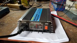
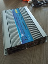
I received my 600 W grid-tie inverter today and hooked it up to the 52 V LiFePO4 battery back and so far all seems to be working as expected. I don't think you need to worry about frying the inverter using a battery, as it will limit the input current to whatever is needed for the max output.
In my case, the battery pack is about 50% SoC, with voltage at about 51 V.
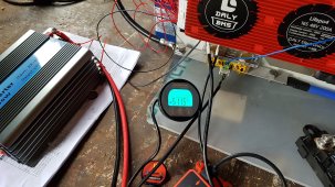
Some photos of the system:
LiFePO4pack.jpgbms3.jpg
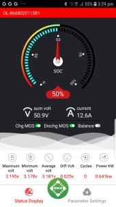
Note this is the mower battery pack waiting for a box etc. I'm using a Daly BMS with bluetooth, and a separate shunt/voltmeter in series.
I had to find a microinverter that could take up to 60 VDC as the LiFePO4 pack fully charged is about 58 V. Most others have a maximum of 55
or less.

volt_micro.jpginverter.jpg
As you can see from the screen capture, the battery pack is discharging at 641 W, so allowing for losses, I expect the microinverter is outputing 600 W. I see that occassionally the battery current changes from 12 A a bit (up to 12.5, down to 11.5).
So after operating for about 60 mins - so far all good!
 
I could not perform the test as explained in the originary post due to suspected defective DC-DC buck converter. (Buying at Aliexpress is tricky...)
I also wonder If an undersized battery could be used for such test even If just for a few seconds. Without current limiting, the test seems risky; not for the inverter but for the battery.

https://diysolarforum.com/threads/testing-grid-tied-inverter-with-battery.32173/

I will try this week the inverter with the solar panels, but this is no new stuff to you. In 1,5 months I will receive another buck inverter, maybe this one is good and I can use it for the test.
Following you on this with interest.
I am waiting on two buck converters from Amazon and one from Alibaba.
Both listed in my previous threads.
So by the looks I may be testing before you.
As I have already fried a local $Aus15 - 3 Amp Buck Converter that was too small.
There will be protective fuses on any more Buck Converters I use in the hope that I won't incinerate them.
 
I'm also interested in using a battery powered microinverter instead of solar panels. The main reason is I've got a 5 kWh lead-acid battery from my ride on mower that is in the process of being replaced with LiFePO4 as per this thread.
So instead of wasting the capacity I am going to use it to provide an additional 5 kWh to my existing 10 kWh home battery. But the problem is that I can't connect another DC input - or mix battery types - into my existing system.
I received my 600 W grid-tie inverter today and hooked it up to the 52 V LiFePO4 battery back and so far all seems to be working as expected. I don't think you need to worry about frying the inverter using a battery, as it will limit the input current to whatever is needed for the max output.
In my case, the battery pack is about 50% SoC, with voltage at about 51 V.
Some photos of the system:
View attachment 74876View attachment 74877
Note this is the mower battery pack waiting for a box etc. I'm using a Daly BMS with bluetooth, and a separate shunt/voltmeter in series.
I had to find a microinverter that could take up to 60 VDC as the LiFePO4 pack fully charged is about 58 V. Most others have a maximum of 55
or less.

View attachment 74878View attachment 74879
As you can see from the screen capture, the battery pack is discharging at 641 W, so allowing for losses, I expect the microinverter is outputing 600 W. I see that occassionally the battery current changes from 12 A a bit (up to 12.5, down to 11.5).
So after operating for about 60 mins - so far all good!
Most interesting.
Looks really good.
Fingers crossed you get long term usage with minimal or no breakdowns.
Lead Acid are too heavy for me.
 
Last edited:
I'm also interested in using a battery powered microinverter instead of solar panels. The main reason is I've got a 5 kWh lead-acid battery from my ride on mower that is in the process of being replaced with LiFePO4 as per this thread.
So instead of wasting the capacity I am going to use it to provide an additional 5 kWh to my existing 10 kWh home battery. But the problem is that I can't connect another DC input - or mix battery types - into my existing system.
I received my 600 W grid-tie inverter today and hooked it up to the 52 V LiFePO4 battery back and so far all seems to be working as expected. I don't think you need to worry about frying the inverter using a battery, as it will limit the input current to whatever is needed for the max output.
In my case, the battery pack is about 50% SoC, with voltage at about 51 V.
Some photos of the system:
View attachment 74876View attachment 74877
Note this is the mower battery pack waiting for a box etc. I'm using a Daly BMS with bluetooth, and a separate shunt/voltmeter in series.
I had to find a microinverter that could take up to 60 VDC as the LiFePO4 pack fully charged is about 58 V. Most others have a maximum of 55
or less.

View attachment 74878View attachment 74879
As you can see from the screen capture, the battery pack is discharging at 641 W, so allowing for losses, I expect the microinverter is outputing 600 W. I see that occassionally the battery current changes from 12 A a bit (up to 12.5, down to 11.5).
So after operating for about 60 mins - so far all good!

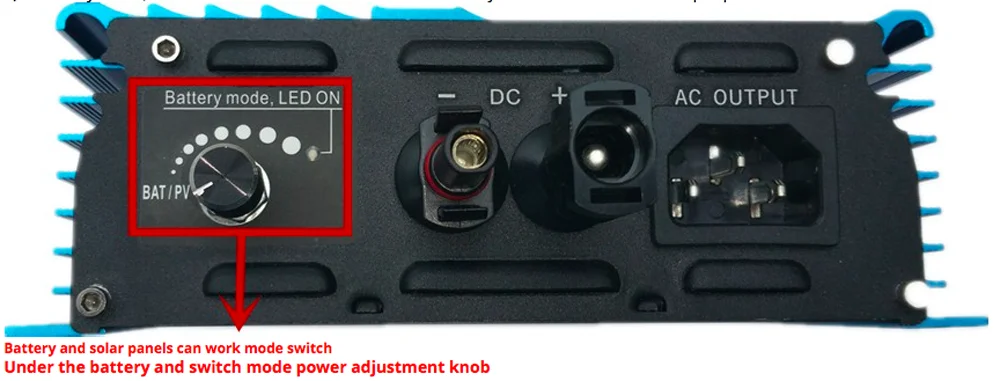
Well, things are about to get interesting now. We have just received the same inverter (just different label on it but clearly same model). I am waiting for the current meters (DC) to start analyzing the performance, the starting power and other parameters of the inverter.

1638868676167.jpeg

As kundip mentioned in a separate post, the inverter can be used on battery mode so long the voltage is over the MPPT range and below the max. input voltage, so 51V is a good spot. But icenov, be careful with running the inverter at full capacity; in some videos of solar youtube guru's it is mentioned that running these chinese inverters at full capacity for hours will significantly reduce their lifespan. I bought it for 2S 16V solar panels and testing with battery may happen or with 12S 2P 18650 battery so I can surpass the 48V from the MPPT range or after I receive a new DC-DC buck converter (which actually can't go over the 48V, so... hope is no problem).

At the same time I am waiting for another MPPT grid tied inverter for a 12V battery and 1 single 12V panel. This is a primitive version of a hybrid inverter and can be used or as a MPPT grid tied inverter from the solar panel or as a grid tied inverter from a battery with regulated discharge [60-250W] (MPPT function off). Both ways of operating can not be used simultaneously. Why I say this is a primitive version of a hybrid inverter is because this ones can operate both mechanisms at the same time while also having much better ranges and often some LED screen or wifi app for smarter programming.


H5eb7aa4e635943b9a72d3116f6ef632dH.png
 
Yes, interesting! I wasn't aware that there was a battery input option available. I did check the starting current draw of the inverter, and it rose slowly from zero to 12 A over about 30 seconds. There is also an adjustment screw for the MPPT range, but no mention of what it does in the manual...
 
I reconfigured my battery pack and now have 550ah pack 20 cells 66 volts. This caused my IQ7x give a red light which in the manual states "DC Resistance Low"

The pack I did the testing on with hooking the IQ7x to a battery was done with a 55 ah pack and I have also hooked it to a larger pack and it worked but now with the big pack it isn't....

Just wanted to let people know so they don't waste money.....
 
I have ran an IQ7x on 24 volts to almost 70 volts increasing one cell at a time.

So how this micro inverter works running it connected to a battery:
It started making power at 33 volts.
It always pulls right around 6.15 amps.
So at 33volt x 6.15amp = 203 watts
Thus at 50 volts x 6.15amps = ~245 watts
It maxed out at 53 volts x 6.15 amps = 326 watts
It makes 326 watts at all voltages above 53 volts.

I never have seen the wattage drop when warm like the specs say....I ran it at room temp.
This was done with a 55 ah pack.
 
I reconfigured my battery pack and now have 550ah pack 20 cells 66 volts. This caused my IQ7x give a red light which in the manual states "DC Resistance Low"

The pack I did the testing on with hooking the IQ7x to a battery was done with a 55 ah pack and I have also hooked it to a larger pack and it worked but now with the big pack it isn't....

Did the 550ah battery happen to share a common/bonded ground with your AC system?
From what I’ve read the iq7 design relies on an isolated DC.

(Following this thread as I’m considering the same approach with iq7x + a 100AH battery)
 
Just came across a relevant video suggesting feeding the inverters above their MPPT range in order to inhibit V/A-seeking competition between multiple inverters connected to the same source.

 
Just came across a relevant video suggesting feeding the inverters above their MPPT range in order to inhibit V/A-seeking competition between multiple inverters connected to the same source.

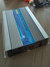
While feeding the inverter with a battery outside of the MPPT range is probable the best option, I can add that I have recently fed a MPPT inverter with a battery within the MPPT range and it has not caused any apparent issue. Also, not sure If as result of the MPPT function, the inverter has not pulled the full load on the battery (small one; 8S2P 18650 cells) which suggests the MPPT found a stable power point even for the battery. The inverter I used is (600W):
1639982542939.png

The only inconvenient is that the power point was still a bit high and as result, I had to disconnect the batteries after 20 minutes to avoid overheating.

After x-mass season I am planning to upload a video about it. It is a test I can repeat many times.
 

diy solar

diy solar
Back
Top