diy solar

diy solar

Will this work for pre-charging inverter capacitors?

The capacitors would only be about 1/2 charged when the Solenoid trips
A solenoid translates electrical energy into physical movement, are you thinking this device would move a switch to an alternative position or are you thinking of a contactor/relay where energising the coil pulls over switch contacts (...and resets them when de-energised)?

If when you say 'solenoid' you mean contactor, then you can do all the time constant tweaking you want, you're still going to have a permanently enrgised heavy duty coil. You mention the contactor you found having a coil resistance of 3R21 ohms with 6.69V required to energise it, that's a constant 2.08A (I=V/R = 6.69V / 3.21 ohms = 2.08A) load or 333Wh per day (P = VI = 6.69V x 2.08A = 13.9W x 24 hours = 333Wh). I did go and have a look for contactors on digikey, the cheapest 12VDC contactor I could find able to switch 150A or more was £74 + shipping. That one required 9V to energise and had an 11R ohms coil, or 0.818A or 177Wh per day. £74 is not cheap, and neither is 177Wh per day.

Now if when you say 'solenoid' you do actually mean a solenoid (i.e. an electromagnet used to physically move something), and that solenoid is used to turn a switch, once switched the solenoid can be de-energised - it's done its job. The way I would imagine this solution working would be:

(1) Press and hold a momentary push button until you hear a 'clunk'
(2) The button would connect the pre-charge resister to the inverter
(3) A similar circuit to that above could be used to momentarily energise the solenoid
(4) The solenoid physically rotates the switch, and is then de-energised
(5) The switch connects the battery to the inverter
(6) To isolate the inverter, physically turn the switch back
(7) Wash, rinse and repeat

Possible? Yes. Practical? No. Pragmatic? Definitely not. Just buy a £1 resister, a £15 rotary switch and suffer the 30 seconds inconvenience it takes to pre-charge manually! ;-)

Regards,
David.
 
A solenoid translates electrical energy into physical movement, are you thinking this device would move a switch to an alternative position or are you thinking of a contactor/relay where energising the coil pulls over switch contacts (...and resets them when de-energised)?

I am talking about an automotive solenoid.
1578328062963.png
I know that this is a miss-use of the term solenoid but since I am specifically talking about the low cost contactor/relay used in cars, I am using the term used in the automotive world. (Apparently the term is used in aircraft too)

If when you say 'solenoid' you mean contactor, then you can do all the time constant tweaking you want, you're still going to have a permanently enrgised heavy duty coil.
Regards,
David.

Yup.... all true. As soon as I saw that spec I realized there is a *lot* of waste in using the Solenoid/relay/contactor.

As an aside, Will often recommends bypassing the load on the BMS by using the same kind of Solenoid/relay/contactor... It will have the same waste problem

Just buy a £1 resister, a £15 rotary switch and suffer the 30 seconds inconvenience it takes to pre-charge manually! ;-)

In most of my installations, I will not be the one at the controls. Consequently, I have to worry about the end user doing it wrong. The less opportunity for it to be done wrong, the better. Unfortunately that may mean more up-front cost and it may mean a less efficient system. (An efficient system is no good if it breaks down)
  1. Right now, the best solution I have seen is the BMS that has a small timed relay that can be set up to do the pre-charge
  2. If the BMS does not have that capability, the best solution I have found is the rotary battery select switch. Even if the user rotates through quickly, they won't get the full surge. (I show a circuit for this in an earlier post.) However, the user could leave the switch in the precharge position and go away thinking the system is shut down. (I can leave a check-list.... but users have an amazing capacity for ignoring instructions)
  3. I am still trying to come up with a better but still practical solution. If I find it, I will share it.
BTW: In the diagram with the rotary switch i posted above, I show a 30 ohm resistor because that is what Will uses. However, in my installations I will be using a smaller resister, perhaps as low as 10 ohms for a 12 volt system. With 10 ohms the pre-charge would be 3 times faster but still less than 1.5 amps. This way, if the user is too quick on the rotary, they will still get a healthy amount of pre-charge as they go through the '1' position. (My SWAG is that with a 10 ohm resistor the pre-charge will be complete in about .25 seconds on a medium/small inveter)
 
However, in my installations I will be using a smaller resister, perhaps as low as 10 ohms for a 12 volt system.
Totally agree, in my tests, even milli-ohm resistances cut the current to manageable levels.

It's quite a useful circuit to re-visit time-constants, inductive load behaviour and the like. Had some fun modelling it :)

Have you every used 'everycircuit' simulator?


I was thinking of maybe using one of those solenoid-operated automatic transfer switches used to break>make grid>local off-grid supplies.

Regards,
David.
 
Totally agree, in my tests, even milli-ohm resistances cut the current to manageable levels.

I have mixed feelings about going too low.
  • In normal operation even a 10Watt resistor would barely notice the current. However, if something bad happens and the resistor is left shorted to ground, it would not handle the current. Consequently, I would like to spec the wattage high enough to handle continuous current at full voltage. That starts getting pretty big as the resistance goes down. The alternative is to put a slow blow fuse in series with it.
  • "manageable" is a relative term. As the pre-charge current goes above a few amps, I start worrying about damage to the switch.
Yes.... I worry a lot. That's what happens after you have a design that you were sure of fail spectacularly in the field. :(

It's quite a useful circuit to re-visit time-constants, inductive load behavior and the like. Had some fun modelling it :)

Have you every used 'everycircuit' simulator?

I haven't had to do an RC time calculation in 40 years (In college and exactly once after that). I had to look it up to remember how to do it. However, you are right, this nerd had fun dusting off the stuff from college.

I have never used Everycircuit. I'll have to look in to it.

I was thinking of maybe using one of those solenoid-operated automatic transfer switches used to break>make grid>local off-grid supplies.

I had not considered those.... something more to look into.
 
Also be advised that many of those high current automotive solenoids are designed for momentary duty only (like supplying the starter motor) and will overheat from coil dissipation if left powered for more than a few minutes.
 
I was finally able to come back to this after some time away, I'm about ready to wire up the switch and have a question about voltage sense. The setup:
- Victron MultiPlus 24 3000
- Blue Sea 6607 4-position rotary switch. position1 has resistor to inverter, position has the inverter
- 24V LiFe battery, + side goes thru switch, - goes directly to inverter

The Victron has a voltage sense input, I'm just using some 14 or 16ga cable for it. Should I wire the positive side of the voltage sense cable to the switch or directly to the pos batt terminal? From what I understand, a voltage sense circuit will be really high resistance, and won't have any parasitic drain when the rotary switch is in the OFF position. Right?

@Justin Laureltec : Do you know? ^^^^^
 
Last edited:
The Victron has a voltage sense input, I'm just using some 14 or 16ga cable for it. Should I wire the positive side of the voltage sense cable to the switch or directly to the pos batt terminal? From what I understand, a voltage sense circuit will be really high resistance, and won't have any parasitic drain when the rotary switch is in the OFF position. Right?

An interesting question that I had not thought of. My guess is you are correct that the current will be very low. Throw an ammeter on it and see. I will be surprised if it even a few milliamps (But I have been surprised before). If you get a measurement please let us know.

I spent a *little* time trying to think of any problem with having the voltage sense hooked up while the primary Positive is disconnected but I don't think there would be.... particularly not with a Victron (They tend to be pretty solid designs)

So.... I would put it on the positive of the terminal, not the switch.

How do you like the victron? My next install is going to include a MultiPlus.

I heard from a Victron employee on the Victron community site.
It shouldn't be a problem, side effects can be: when multi is powered from AC with battery disconnected: you can get a battery sense error when the voltage difference between the sense input and battery terminals is too big.

So, I'm going to go ahead and run my voltage sense cable directly between inverter and battery. I really like the Victron so far, but all I have done is initial testing and I haven't pushed it at it's spec'd limits (only 50A of charging on only 1.5kWh of output), I do like the configurability, but one thing I hope they add to the firmware is an option to stop the absorption phase when the charge current drops below a given point, rather than just based on time. But, it's not such a big deal that I wouldn't recommend the product.
 
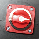
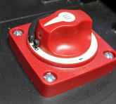
Ok, I FINALLY got some time to spend on my build, so I wired up the pre-charge circuit today. It's a Blue Sea M-6007 switch and a 20 50W resistor. I have a 24V system.
precharge-1 resistor.jpgprecharge-2 resistor wired.jpg
precharge-3 switch-back.jpgprecharge-4 switch-front.jpg

First I soldered some 10AWG wire on the resistor. The wire doesn't need to be this bug, it'll carry no more than ~1.5A. But, I had this super flexible wire already, and I had 3/8 ring terminals for 10AWG wire. To solder it, I tinned the tabs on the resistor, pushed the strands of the wire on the tabs, formed them back into a sort of twisted bundle, then soldered all that and covered it with heatshrink.

Next, I wired the switch. The thing to remember is the switch connects Output to either 1, 2, or 1+2. So in this setup, Output is the battery, 2 is the inverter, and the resistor runs between 1 and 2. See previous posts in this thread on why this works.

I tested this with a multimeter before actually connecting to a battery. One probe on Output and one on the inverter cable.
Off - No connection
1 - 20.5Ω
1+2 - 0.5Ω
2 - 0.5Ω

After checking and re-checking several times, I turned the switch to off and hooked this up to the inverter and battery. I switch to 1, counted a few seconds, then to 1+2. Verified it all works as expected! The resistor is connected as soon as the switch snicks into 1. As I move to 1+2 and 2, the inverter stays on. As soon as the switch leaves 2 on it's way to off, the battery is disconnected.
 
Last edited:
UPDATE:
I printed a block to prevent the rotary switch I had installed from turning from OFF directly to 2. Then I put a cap head screw in the switch handle so it hits the block. My first attempt had the screw too high, and it was a little hard to turn the switch. Block is glued down with Goop so it'll come off if needed.

switch with block - top.pngswitch with block - front.png

Also, I know have a feel for how long pre-charge takes. Because the time it takes depends on the capacitance on the inverter, the battery voltage, and the resistance of the pre-charge circuit, it'll only be a rough guide for others. With a 27.7V battery, thru a 20Ω resistor to the Victron MultiPlus 24V 3000VA, I get to about 24V in about 4-5 seconds. I usually move the switch to 1+2 after that, the inrush from a 3V difference shouldn't be a problem for anything. I'm thinking about swapping in a 10Ω resistor to speed this up. But there's actually nothing wrong with things as they are, I'm just tinkering at this point.
 
Ah Filter. In your case I can see the desire to disconnect completely. But your situation works fine with a check-list:

Powering up
1) Confirm Inverter Switch is OFF.
2) Turn switch X to position 1 count to five.
3) Turn switch X to position 2.
4) Turn ON inverter.

Powering down before leaving
1) Turn OFF inverter.
2) Turn switch X to OFF.
I know this thread is fairly old and have not gotten to the bottom of it yet. I am new to inverters and solar but have came a long way, I thought, until now ugh! I cannot seem to wrap my head around how to charge/discharge capacitors NOW after reading this far lol I thought it was as simple like in Wills video. This is my scenario. 3000w/6000w 12v wzrelb reliable inverter, battery cables 1/0, 2 npp 6v 180ah batteries in series. I will not have a momentary switch installed, it will be identical to Will’s video touching the resistor to the battery to get precharge. At first I was going to use 20w 30ohm resister like in the video, but after reading all of this which REALLY confuses me now. Could I still use that resister and touch them or is there the thermistor I need to use? That’s where I’m stumped because 12v SERIES, set up. Thanks to anyone who helps out with this! BTW, my system will be set up, used for a week, then taken down and transported back home from cabin 1x a year.
 
Just touch and done.

I use these with rigid leads that make it stupid simple ?

I knew it was good to charge inverter capacitors and discharge them is what led me to this thread. Then got completely confused trying to follow the thread, just knowing there are variables way over my head, but still want to be safe. Thanks for the reply!
 
I knew it was good to charge inverter capacitors and discharge them is what led me to this thread. Then got completely confused trying to follow the thread, just knowing there are variables way over my head, but still want to be safe. Thanks for the reply!

Glad to help.

And I never bother to discharge the caps. Time does that ?
 
@Delaware79 ,

If you are doing the one-time resistor pre-charge, the PTC resistor is not needed. It is strictly a safety for a miss-use case when you have the switch with the built in pre-charge.

The value of the resistor for the one-time pre-charge can be almost anything from 3-50 ohms.
 
@Delaware79 ,

If you are doing the one-time resistor pre-charge, the PTC resistor is not needed. It is strictly a safety for a miss-use case when you have the switch with the built in pre-charge.

I’m not sure if my inverter has a built in precharge switch, I’ll have to research as the manual doesn’t explain much. It’s good to know when the precharge is needed. If mine has a built in precharge switch, would I be hurting it if I do a precharge not knowing whether it has one or not? I’m not sure I’ll be able to find that anywhere if it has one or not
The value of the resistor for the one-time pre-charge can be almost anything from 3-50 ohms.
@Delaware79 ,

If you are doing the one-time resistor pre-charge, the PTC resistor is not needed. It is strictly a safety for a miss-use case when you have the switch with the built in pre-charge.
I’m not sure if I have the switch with the built in precharge
The value of the resistor for the one-time pre-charge can be almost anything from 3-50 ohms.
 
I’m not sure if my inverter has a built in precharge switch, I’ll have to research as the manual doesn’t explain much. It’s good to know when the precharge is needed. If mine has a built in precharge switch, would I be hurting it if I do a precharge not knowing whether it has one or not? I’m not sure I’ll be able to find that anywhere if it has one or not

I have never seen an inverter with a built in pre-charge. A while back someone on the forum claimed theirs did but it turned out it did not.

As far as I know *all* inverters have a large capacitor bank hooked directly to the DC input. When you first hook up the DC there will be a very short but huge current spike. This will appear as a nasty spark when you touch the leads together.

When you disconnect the DC, the inverter capacitors will hold a charge for a little while, but the charge will usually drain off in a few minutes. (The speed it drains off will be determined by the Capacitors and the inverter circuitry.)

The large surge is not good for FETs in a BMS. Furthermore, some BMSs will detect it as a short and immediately shut off. What happens next is dependent on the BMS. Some, BMSs will retry after a short and since the first spike partially charged the capacitors, it might well work the second try. Other BMSs will require manual intervention to turn them back on.

Once the Battery/BMS/Inverter is all hooked up and operating, there will not be another need to pre-charge till the Battery is disconnected from the Inverter.
 
Back
Top