Solar Canada
New Member
Hello,
I am setting up a Remote Solar Generator/Charger using the Schneider Conext SW4048 product, along with the associated Schneider A/C and D/C boxes manufactured by Schneider for combination with the SW Product Line. I have a technical/wiring question I need some assistance with.
For reference, this system will be housed in an enclosed trailer and be used in Ontario, Canada to run our installation equipment while on-site doing Solar Installations for my PV company (Electric Ladder Equipment Lift, Power Tools, etc.) I will be using PV Panels mounted on the Enclosed Trailer to charge my 280Ah 48V LifePo battery bank predominantly via the Schneider 60 150 Charge Controller, however I would also like to be able to charge from Grid power (120V) using the SW Built-In Charger (I will be using only L1-120V for charger effectively limiting charging power to 50% but I'm ok with this). The issue I have is determining how to complete the system wiring, specifically with respect to the Neutral-Ground Bond and how to wire this.
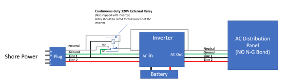
I plan to connect the Inverter A/C Out L1-L2 to a Inverter Load(s) Distribution Panel that will be used to distribute power to a number of 120V/240V A/C circuits I am installing. When completely operating the system off-grid (most of the time), the Neutral-Ground Bond should exist in the Inverter Load Distribution Panel I will install (as I understand it) as it will be operating as the defacto Main Distribution Panel. However, when I connect the SW charger to Grid power a second Neutral-Ground Bond will exist in the Grid Tie system that I am connecting to. How is this typically handled in a system like this and what would be the best way to complete my wiring? When investigating this online all of the systems I have found have the Inverter connected to Grid full time which provides this Neutral-Ground Bond. In this instance my Inverter Load Distribution panel would be classified as a Sub Panel and I would not connect the Neutral-Ground, however my situation is different with intermittent Grid Connection only when required.
Can someone shed some light on how to complete my set-up? This is my first attempt to set up a system like this and I am not an Electrician so don't want to make any silly mistakes.
Thanks in advance for your input and information.
Pete
I am setting up a Remote Solar Generator/Charger using the Schneider Conext SW4048 product, along with the associated Schneider A/C and D/C boxes manufactured by Schneider for combination with the SW Product Line. I have a technical/wiring question I need some assistance with.
For reference, this system will be housed in an enclosed trailer and be used in Ontario, Canada to run our installation equipment while on-site doing Solar Installations for my PV company (Electric Ladder Equipment Lift, Power Tools, etc.) I will be using PV Panels mounted on the Enclosed Trailer to charge my 280Ah 48V LifePo battery bank predominantly via the Schneider 60 150 Charge Controller, however I would also like to be able to charge from Grid power (120V) using the SW Built-In Charger (I will be using only L1-120V for charger effectively limiting charging power to 50% but I'm ok with this). The issue I have is determining how to complete the system wiring, specifically with respect to the Neutral-Ground Bond and how to wire this.
I plan to connect the Inverter A/C Out L1-L2 to a Inverter Load(s) Distribution Panel that will be used to distribute power to a number of 120V/240V A/C circuits I am installing. When completely operating the system off-grid (most of the time), the Neutral-Ground Bond should exist in the Inverter Load Distribution Panel I will install (as I understand it) as it will be operating as the defacto Main Distribution Panel. However, when I connect the SW charger to Grid power a second Neutral-Ground Bond will exist in the Grid Tie system that I am connecting to. How is this typically handled in a system like this and what would be the best way to complete my wiring? When investigating this online all of the systems I have found have the Inverter connected to Grid full time which provides this Neutral-Ground Bond. In this instance my Inverter Load Distribution panel would be classified as a Sub Panel and I would not connect the Neutral-Ground, however my situation is different with intermittent Grid Connection only when required.
Can someone shed some light on how to complete my set-up? This is my first attempt to set up a system like this and I am not an Electrician so don't want to make any silly mistakes.
Thanks in advance for your input and information.
Pete