diy solar

diy solar

battery charging design

dudeinak

Less talk, more fish!
Joined
Feb 11, 2020
Messages
9
This may be outside of the purview of this forum, but am hoping to enlist the knowledge contained herein to help my with my project. This is a boat project, so theres that. I have two batteries that need to be separated into a start and house battery isolated from each other, yet charged from same alternator. Would like to add a solar panel in near future for battery charge maintenance when on overnite trips
My confusion is in the design. What components are best, where and how many fuses to include, and what device to use for charging both batteries while maintaining isolation. Thanks for the forum.
 
This is what I will be putting into my sisters boat if the batteries ever get here. (Stuck in china right now)
1581486844023.png

I have not yet been to the boat so I still don't know exactly what will be done for fusing.

Edited to add the following:
There will likely be additional fuses to what is shown above. This drawing should not be used for a fusing plan
 
Last edited:
You can use diode type isolators, work are widely available, are not elegant or efficient.

You can use relay/contactor type, a little better. Blue sea and a scad of other companies make them. SCR, ACR etc. Allows combining for emergency on your boat. Not too elegant, but i think generally better than diode isolation.more accurate amd efficieng.

The best way i can think of to both totally isolate and charge accurately are dc to dc or battery to battery charge controllers. They are smart chargers and efficient. I do not recall if any will combine for a jump start.
 
Most of the appliances are existing. The project is to dump the old AGM house battery, put in LiFePO4 and add the inverter.

Notice the separation between the starter and house batteries.
* The AC charger on the starter battery is an existing Charger I will leave in place
* The Renogy DC-DC charger is there to charge the house battery when the engine is running.
* The emergency start switch and relay is kinda like jumper cables between the house battery and the Starter battery. Hopefully it will never be used.
 
The dc to dc chargers require a fuse on both battery positives leading to amd from the controller.
 
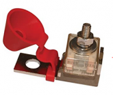
I jse the single tab (ring terminal) mrfb fuses.
Are you talking about hanging one of these off the DC-DC converter?
1581488975814.png
Will it go into the terminal block on the converter?

I have mixed feelings on these. You can put them right on a post (good), but it adds leverage and mechanical stress to the post (Not good).
 
They go on the battery post or on a short leash. 4" or as close as possible is recommended. 6" to wherever is safe is likely. These are stud mount. I use the brass battery stud adaptors for automotive or the hold down bolt if its that type terminal.

With the way they lay it will not hurt the terminal. Super fine strand flex cables and creative wire management will provide a reliable lug integrity.

On the house battery side it would likely be a bus involved. Shoot, its a boat maybe on both if its not there already.

If its a bus different story, you dont need the tab mount, just the fuse.

I dont know about just slapping the fuse down onto the battery terminal, maybe if its a bronze one..... not thinking that is within its use. They are invariably used on a bus or special terminal made of copper or plated copper. Phosphor bronze and other copper alloy terminals would meet that material quality, roughly.

There is nothing wrong with a short cable to a mounting surface where the fuse and secondary cable can be secured. That is how the vehicles and craft are built anyhow.
 
The dc to dc chargers require a fuse on both battery positives leading to and from the controller.
On the starter battery side, I will fuse the 6 Gauge line where it taps off the battery (But I do notice I don't have that indicated in the drawing).
I will also put a fuse on the output of the DC-DC converter. However, I don't understand why there would be one at the input terminal of the converter. Please help me understand.

The fusing rules of thumb I use:
  • Breaker or Fuse for 1.25xexpected max current.
  • Any current source should have a fuse or breaker at the source with a limit that is small enough to protect any wire between it and either the next fuse or a load.
  • At the point were a smaller gauge wire is coming off of a larger gauge wire, there should be a fuse or breaker that is small enough to protect the smaller gauge wire.
Exceptions:​
  • If a current source has adequate internal over-current protection, a fuse/breaker at the source may not be needed *if* the wire coming from the source is large enough to handle the current before the over-current protection kicks in.
  • There is generally not a fuse between a starter battery and the starter.
 
Are you talking about hanging one of these off the DC-DC converter?
View attachment 7172
Will it go into the terminal block on the converter?

I have mixed feelings on these. You can put them right on a post (good), but it adds leverage and mechanical stress

Both battery positive terminals. The batteries while "isolated" for load purposes and alternator charging are connected together through the b2b circuit. In that line both extreme ends (both battery terminals) are fused. Think of the whole shebang as a wire with a fuse on either end.
 
I guess if the internals of the device have smaller wires, an external fuse that is small enough to prevent them from burning is appropriate.... but at that point you could put the fuse at the beginning of the wire leading to the device. In this case it would be the fuse where I tap my
Both battery positive terminals. The batteries while "isolated" for load purposes and alternator charging are connected together through the b2b circuit. In that line both extreme ends (both battery terminals) are fused. Think of the whole shebang as a wire with a fuse on either end.
At the batteries... yes. I was confused. I thought you were saying put one at the positive terminal of the input to the DC-DC converter.
 
BTW: There needs to be one at the output of the DC-DC converter as well.
1581491706260.png
Like I said, I have not been at the boat so I have not settled on a definite fusing plan. My drawing in the earlier post should *not* be used as a guideline for fuses. (I added this warning to the post with the drawing)
 
Wow, thanks for all the input and design. My situation is complicated by the fact that my boating is all on salt water. My wiring hence has to be all marine grade. The current setup is to AGM batteries that are essentially connected in series. What happens now is, when i start the engine my chartplotter shuts down, so that is why I need to make the change, plus if course if one battery drains they both do. I am considering adding a second battery to the house side, run in series, to increase watts for a big enough inverter to handle the onboard electric heater (happy wife, more fishing)
And am confused if i would need a second dc to dc (like the renogy), or if I could charge multiple batteries from one. Thanks so much for the input.
 
Wow, thanks for all the input and design. My situation is complicated by the fact that my boating is all on salt water. My wiring hence has to be all marine grade.
Yup. My install is going into a NordicTug 26. I will be ripping out some non-marine wire and replacing it with Marine Wire. It is amazing how poor/dangerous of a job some people do on a vehicle they can't easily escape from.

I am considering adding a second battery to the house side, run in series, to increase watts for a big enough inverter to handle the onboard electric heater
Do you mean run the second battery in parallel? If you run it in series you double the voltage....

An electric heater is designed to take a LOT of energy and turn it into heat. You may want to run some numbers to see how big your battery would need to be.

(happy wife, more fishing)
OK... Now I understand.... Make that battery as big as it needs to be!!!!! :LOL:

If your engine is diesel, you might want to consider getting one of the small diesel cabin heaters.

And am confused if i would need a second dc to dc (like the renogy), or if I could charge multiple batteries from one. Thanks so much for the input.

You shouldn't. Even if you did, your alternator might not be able to handle it.
 
Sorry, yes, parallel. Gas engine. Small heater. Soon as I can get the boat uncovered from the latest snow fall, will check the numbers. Am wondering about fuses; in a saltwater environment, the biggest danger, asie from ignition spark in an improperly ventilated engine compartment, is the upper corrosion that introduces resistance hence heat hence boom. ?
I imagine Bluesea is the best source??
Btw, love the Nordic Tug.
Thanks.
 
If its a bus different story, you dont need the tab mount, just the fuse.

I dont know about just slapping the fuse down onto the battery terminal, maybe if its a bronze one..... not thinking that is within its use. They are invariably used on a bus or special terminal made of copper or plated copper. Phosphor bronze and other copper alloy terminals would meet that material quality, roughly.

I may have misunderstood what was being said here, but in case I didn't: an MRBF fuse always needs to be mounted to an MRBF fuseholder, it must not be mounted directly to a bolt. The reason being: if you study the construction of the fuseholder, the center threaded rod is insulated from the bottom plate so that the only connection between the lug (going off to the load) and the fuseholder is through the fuse. Thus when the fuse blows, there's no way for current to pass from the bottom mounting plate to the threaded post. If you just put an MRBF fuse on a regular busbar post, nothing at all will happen when the fuse blows because the the busbar post isn't insulated from anything else... current will just pass through the post instead of the fuse.
...Sorry, I'm not sure if my explanation of that makes a lot of sense (or even if it was necessary), but I just want to make absolutely certain no one is trying to use MRBF fuses without the fuseholder, because they don't work without it... they'll pass all the current you could want, they just won't stop it.
 
Sorry, yes, parallel. Gas engine. Small heater. Soon as I can get the boat uncovered from the latest snow fall, will check the numbers. Am wondering about fuses; in a saltwater environment, the biggest danger, asie from ignition spark in an improperly ventilated engine compartment, is the upper corrosion that introduces resistance hence heat hence boom. ?
I imagine Bluesea is the best source??
Btw, love the Nordic Tug.
Thanks.
Blue Sea/Bussman (Bussman is OEM for all Blue Sea's fuses and circuit breakers). Just double-check that everything is ignition-protected; the MRBF fuses referenced above are, as well as almost all (up to 500A) of the Bussman ANL fuses and also the series 187 circuit breakers and... well, the list goes on. Look for "ignition protected" and "tinned copper" because the tinned copper is marine-rated for anti-corrosion.
 
Back
Top