diy solar

diy solar

First DIY Electrical Setup

jacobberke

New Member
Joined
Feb 16, 2020
Messages
12
Hey everyone, so I'm building inside a Promaster 136WB camper van and been following Will's videos. I've come up with this so far, however, I'm stuck on how I would proceed with the 12V DC portion to the fusebox. I would be doing a 12V system with the all in one system and two Battle Born batteries. Please let me know how you would set up the DC portion or anything else I should change. Thank you.
 

Attachments

  • Electrical Setup.pdf
    122.5 KB · Views: 14
  • Capture.PNG
    Capture.PNG
    333.1 KB · Views: 26
Last edited:
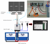
Yea, quite blurry zoomed in. Is that a MPPT controller/inverter under the panels? If so : Does it have an internal transfer switch? If so:

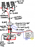
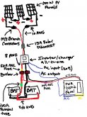
For your AC input (assuming this is a 30amp rig IE only 1 AC leg not 2 like a 50amp rig) you take out your circuit box (don't be plugged in), locate your MAIN breaker (30a) then disconnect the black from the breaker, white from the bar AND ground from the bar. Wire nut those wires individually to a length of 10/2 Romex (has black, white, copper ground wires) that Romex then connects into the AC INPUT of the inverter, black is L1 white is N1 and ground is that screw or whatever, just make a copper wire tail, screw it to ground and wire nut your INPUT and OUTPUT ground to the tail. Then take a fresh peice of 10/2 Romex and wire that black to L2, white to N2 and ground as already stated and run that Romex back to the panel and Black goes back into the breaker, white to the neutral bar and bare copper to ground bar. And it's done. Your whole house can now be run from the inverter.

If it happens to be a charger also disconnect your internal converter charger.

TLDR: Don't do any of the above if you're afraid of electricity, drunk, on drugs, color blind, colour blind or just flat out blind.
 
I'm not sure what you are asking for.

You are going to have an entire 120V setup with the batteries and the LV2424.

Why are you concerned with 12V?
Your drawing shows no connection with 12v.

Are you wanting to charge the batteries with the alternator?
If so, then your "A/C" source could be another separate 12V inverter powering the "A/C Input" of the LV2424.
 
Last edited:
I'm not sure what you are asking for.

You are going to have an entire 120V setup with the batteries and the LV2424.

Why are you concerned with 12V?
Your drawing shows no connection with 12v.

Are you wanting to charge the batteries with the alternator?
If so, then your "A/C" source would be another separate 12V inverter powering the "A/C Input" of the LV2424.
I want a 12V connection but I don't know how to implement it. I want to use it for the Maxx air fan, lights, USB plugs, and refrigerator. I don't know where to put it into this schematic. I hear it is more energy-efficient.
 
Okay downloaded the slightly Engrish maual. What you have is a solar charge controller/inverter hybrid. I've never installed one so good luck with the manual that can be downloaded from the ebay link.
 
But your van already has 12V everywhere. Right?

If you have 12V from the Van, why do you want to put into the 120V AC inverter, and then Invert it back to 12V DC? Just use what is already in the van.

You could run 12V stuff directly from the batteries(Battleborn) and that would work fine also.

These things are everywhere:

If all you need is a 12V plug, well it's just 12V DC.
Go to any auto parts store and viola, 12V DC.
 
I think OP is wondering how to power other DC devices, not necessarily part of the solar setup.

This is typically done via a DC consumer panel. Such things look very similar to AC consumer panels but are generally smaller and usually use automotive-style 'blade' fuses rather that circuit breakers. I have one for my Caravan, it distributes DC power from my battery (well, actually it is supplied via a Victron BatteryProtect) to all the various DC circuits e.g. water pump, refrigerator, lighting, alarm, cooker igniter, aux plugs etc.

This is the model fitted to my caravan:

2020-02-18_13-47-08.png

It is a hybrid AC/DC distribution panel + charger but you can get very simply DC-only distribution panels, for example:

2020-02-18_13-48-27.png

Or even simpler:

2020-02-18_14-02-48.png

These and similar products are manufactured by a company called BCA Group in the UK, but I dare say the US will have her own manufacturers. A good selection of DC distribution devices can be researched at 12-Volt Planet.

My DC distribution system looks something like this:

dc system.png

Edit: Added link to 12-Volt Planet.
 
Thanks for the info. I believe I found it out. Here's what I'm planning to do my Van electrical setup:
 

Attachments

  • Electrical Schematic.png
    Electrical Schematic.png
    18.4 KB · Views: 12
Looks good, but I would urge caution:
  1. 2/0AWG cable is only rated for 225A (according to here) but you are protecting it with a 300A fuse.
  2. 6AWG cable is only rated for 95A but your are protecting it with a 100A fuse.
I've changed the 300A fuse to 200A and left the 100A ANL fuse the same, it is going to a distribution panel and all the other DC devices will have another fuse. How critical is this because I can't find a 95A fuse?
 

Attachments

  • Electrical Schematic.jpg
    Electrical Schematic.jpg
    275.6 KB · Views: 7
I'm sure it will be fine. A short is likely to draw significant current and 5A over rating won't matter too much. I am assuming that you're not planning to draw anywhere near 100A in operation, though.
 
For wiring protection 125% is fine so the 100A fuse is appropriate. The 300A fuse would have failed that metric but you have already changed it.

@FilterGuy wrote a thread about this complete with a professional looking slide deck which covers the topic quite well
 
Just to be clear about the 125% rule of thumb. Fusing at 125% is referring to the expected current under normal use. The cable *must* be rated to handle all of the current the fuse will allow.

Example: If in normal use, you expect 80 amps, you can put a 100 Amp fuse. However, that means the wire has to be able to handle at least 100 amps.

1582214184486.png

I will go back and see if I can still edit the other thread about fusing to make this clear.

Note: The implication here is that you don't want to put larger breakers/fuses than you need... it will drive putting large wires than you need.
 
Just to be clear about the 125% rule of thumb. Fusing at 125% is referring to the expected current under normal use. The cable *must* be rated to handle all of the current the fuse will allow.

Good point but if I am looking at this correctly the DC panel can only pull a max load of 100A since there is a 100A fuse there.

The inverter, at 800W, 12v should pull a max of 67A if my math is correct.

So the expected max possible current is 167A correct?

So no conflict with the 125% rule since the wire can carry 225A and 125% of 167 is only 209A or am I missing something?? (and that is quite possible)
 
You have to look at what will happen if there is a short circuit.

I re-drew part of the diagram (Please let me know if I got it wrong.)

1582225459892.png
  • The 200 amp Battery fuse is protecting the 2/0 wires going to the bus bars. This is good. If there is a short on the 2/0 wires there can be up to 200 amps and the wire can handle that. (but no more) The fuse should be as close to the battery as possible.
  • The 100 amp fuse is protecting the 6AWG wires from the bus bar to the distribution panel. This is bad. If there is a short on the 6AWG wire, there will be up to 100 amps on a wire that is only rated for 70 Amps. For a 100 amp fuse, the minimum wire should be 4AWG. The fuse should be as close to the bus bar as possible
  • The 50 amp fuse is protecting the 8AWG wires from the bus bar to the AIO. This is bad. If there is a short on the 8AWG wire, there will be up to 50 amps on a wire that is only rated for 40 amps. For a 50 amp fuse, the minimum wire should be 6AWG. The fuse should be as close to the bus bar as possible.
  • The 50 amp fuse is on the AIO circuit. The 800 amp inverter of the AIO could draw 67 amps (or more). If you never max the 800W of the inverter, the fuse would not blow, but you if you do, the fuse will blow unnecessarily. The circuit should have at least a 70 amp fuse and the wire should be at least 6AWG. Note: I have not read the manual for the AIO. It may recomend a larger fuse which would mean the wire would also have to be larger.
 
Last edited:
Back
Top