diy solar

diy solar

How do you ensure you are getting a cold weld in a crimp?

FilterGuy

Solar Engineering Consultant - EG4 and Consumers
Joined
Nov 26, 2019
Messages
8,008
Location
Los Gatos CA
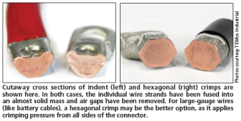
Does anyone know a good test to ensure a crimping process is creating a good cold-weld? I have always used a crimper and just assumed I was getting a good crimp. I have also cut a few crimps in half to check that it looks like solid copper. However, is that sufficient? Is there something else that can be done to verify a cold weld was achieved?

I am working on some stuff right now that uses some non-standard crimping and I am wondering if there is a good way to verify the process? (Destructive testing is OK).
 
Neutron imaging:


Neutron imaging:


I love excuses to buy tools but that is a stretch.... I don't think I could sneak a Neutron Imaging system past my wife!! ?
 
Just send a really big current through it.......
How does a really big current determine if a cold weld has been made or not?

I have 450A @ 8v on speed dial, but not sure if I could put it to use to quantify the question here.
 
Sacrifice a sample piece of wire and lug. Hack saw it through crimp. It will look close to a solid piece of copper.

This assumes you have a quality crimper that is consistently repeatable.

You would be surprised how much resistance there is where the lug tube necks down from end of wire to flat of lug. Keep away from cheap thin wall gauge metal lugs.

1644547620381.png
 
In my marine connection days. We always crimped and soldered. (Flux applied to lug, before crimping)
The solder, also blocked contamination ingress.
 
If using a hydrolic crimper you could make 3 or 4 cables and lugs at different pressure rates, one being your desires pressure and the others less. Then test for voltage drop on each to get a baseline. Then cut them each open to see how they look. If your target pressure looks good then u'd have some idea of a good and questionable voltage drop.
 
In my marine connection days. We always crimped and soldered. (Flux applied to lug, before crimping)
This always brings up near-religious debate..... Some folks really think soldering is a bad idea. I have mixed thoughts on it.... I lean toward thinking it is a good idea. The one thing folks have mentioned that makes me wonder is that the solder will wick up the wire. At the end of the solder creates a spot that could be prone to stress wear..... I don't know if this is a big deal or not.
 
This always brings up near-religious debate..... Some folks really think soldering is a bad idea. I have mixed thoughts on it.... I lean toward thinking it is a good idea. The one thing folks have mentioned that makes me wonder is that the solder will wick up the wire. At the end of the solder creates a spot that could be prone to stress wear..... I don't know if this is a big deal or not.
Off grid garage Andy (take it with a grain of salt YMMV) says solder is not good. Creates a second connection point (so to speak) for failure inside the lug
 
Apply heat to the bottom of the lug, and only Apply just enough solder to fill the lug. I never had a wicking problem. If anyone did, the connection was remade.
These were high vibration installations.
 
Apply heat to the bottom of the lug, and only Apply just enough solder to fill the lug. I never had a wicking problem. If anyone did, the connection was remade.
These were high vibration installations.
if soldering crimped lug, this is how i would try. the environments i'm building for are not high moisture

soldering kind of like art; applying heat to opposite side of lug, ensures the solder will wick in the desired direction (into the lug)

heating the conducting wire, might be more likely to cause excessive wicking.

i'm ignorant of exactly how to do it, so i rely on a crimp tool with long arms for good leverage.

this makes me want to try out what @MrM1 mentioned
If using a hydrolic crimper you could make 3 or 4 cables and lugs at different pressure rates, one being your desires pressure and the others less. Then test for voltage drop on each to get a baseline. Then cut them each open to see how they look. If your target pressure looks good then u'd have some idea of a good and questionable voltage drop.
or at least, perhaps test large cables like this at least once after crimping, and perhaps redo if resistance comes back higher than expected.
 
I used to solder my 2/0 lugs on. I used Excelene welding cable as the insulation can take the heat.
 
Hermeticity test?
Gross leak: connect a hose to it, pressurize and immerse in water (only useful if your terminals don't have closed-toe shoes; if they do, drill a vent hole in the toe.)

If you want to do fine leak, that typically involves helium and an atomic mass spectrometer, or radioactive isotopes.
So I suggest you stop at gross leak.
 
I have one at my lab :)
Throughout the years I have always asked for a SEM, scanning electron microscope when it came time for budgeting test equipment for the upcoming year. It was more of a joke than anything real. When I got to Creare and asked for one, I was told, "We don't need another one." It was an amazing place overun with PHDs.
 

diy solar

diy solar
Back
Top