diy solar

diy solar

New PowerMax Lithium Series Converter/Chargers

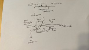
I've modified my converter with an external switch to select 2 different voltages. I also ran 12V from the converter to the switch panel to power an LED to show which mode is selected. The DPDT slide switch I used doesn't stick out beyond the little panel. So it can't be switched mistakenly.
Those voltages result in 3.3 V/cell and 3.55 V/cell
Now you need to incorporate one of these and set the adjustment where it needs to be for automatic switching when the tail current reaches your desired setpoint....
 
For 13.4 and 14.2, use 680 Ohm, For 13.2 and 14.2 use 510+68 ohm in series. Set the low voltage with the switch open. Then when the switch is closed the resistor is placed in the circuit, the voltage rises.
 
Last edited:
Where is this resistor placed? Aren't the output terminals soldered into the board?
It's placed across the voltage adjustment pot. The pot itself has 3 pins. But 2 of them are shared by a single PCB pad. So, in effect, it has only 2.
Once you look under the circuit board by the pot, it'll be pretty obvious. Of course this is for the PM4. I don't know if it would be the same for the PM3-LK & LKL.
Ok, so assuming the 14.2 and the 13.4 voltage setpoints.....when the switch is closed, you are effectively putting the 680 Ω resistor in parallel with respect to the existing resistance of the adjustment pot....correct? When the switch is open, the resistance of the pot by itself will be providing whatever resistance that is needed to produce the 13.4 voltage output.....correct?
 
That is way cool.
You're using the fixed output then? But can switch it manually for charge or float?
Chris.....what I believe he is saying is that the added resistor has been placed in the adjustment pot control circuit and not anything to do with the Power Supply output load current. The resistor is basically providing a fixed resistance that allows the output voltage of the power supply to be at a certain setpoint.
 
It's placed across the voltage adjustment pot. The pot itself has 3 pins. But 2 of them are shared by a single PCB pad. So, in effect, it has only 2.
Once you look under the circuit board by the pot, it'll be pretty obvious. Of course this is for the PM4. I don't know if it would be the same for the PM3-LK & LKL.
The PM-3-LK is the same as you describe. I have a 10 turn pot I'm going to install. The 120 line has a SSR that my electroDacus SBMS0 controls then I can just set it where I want at any given time.
 
Exactly. Below are the voltage/resistance measurements I took.
14.4 182
14.2 198
14.0 222
13.8 242
13.6 263
13.4 280
13.2 302

So if you set the converter to 13.4V, the pot ( plus a parallel resistor already on the board) is 280 ohms. By adding a 680 ohm in parallel, you reduce it's overall resistance to 198 ohms. That matches up with 14.2V. To make the upper voltage tunable after the fact, install a 510 ohm fixed resistor in series with a 1k pot. This should allow you to adjust the high voltage between 13.9 and ~14.5 if the low voltage is set to 13.4. If you set for 13.2, that adjustable range is then about 13.7-~14.5
 
The PM-3-LK is the same as you describe. I have a 10 turn pot I'm going to install. The 120 line has a SSR that my electroDacus SBMS0 controls then I can just set it where I want at any given time.
I would be careful using an SSR to do the switching. The currents involved are in the low milliamp range. Experiment first.
 
Now you need to incorporate one of these and set the adjustment where it needs to be for automatic switching when the tail current reaches your desired setpoint....
I have a BMV-702. I could tap into the VE.Direct and read current off the TX pin with a microcontroller then switch the resistor as well.

I've considered replacing the pot completely with a solid state pot controlled via uC to give me complete control over voltage. Once that's done, I can add a bluetooth module and control the output completely using inputs from the Victron shunt to monitor current, remote voltage sensing, etc. I'd have complete control over the converter via a bluetooth app.
 
Exactly. Below are the voltage/resistance measurements I took.
14.4 182
14.2 198
14.0 222
13.8 242
13.6 263
13.4 280
13.2 302

So if you set the converter to 13.4V, the pot ( plus a parallel resistor already on the board) is 280 ohms. By adding a 680 ohm in parallel, you reduce it's overall resistance to 198 ohms. That matches up with 14.2V. To make the upper voltage tunable after the fact, install a 510 ohm fixed resistor in series with a 1k pot. This should allow you to adjust the high voltage between 13.9 and ~14.5 if the low voltage is set to 13.4. If you set for 13.2, that adjustable range is then about 13.7-~14.5
I'm trying to visualize this in my head........did you happen to make a schematic drawing of the additions that you made?
 
I have a BMV-702. I could tap into the VE.Direct and read current off the TX pin with a microcontroller then switch the resistor as well.

I've considered replacing the pot completely with a solid state pot controlled via uC to give me complete control over voltage. Once that's done, I can add a bluetooth module and control the output completely using inputs from the Victron shunt to monitor current, remote voltage sensing, etc. I'd have complete control over the converter via a bluetooth app.
Maybe I'll fiddle with this idea a little. The Victron VE.Direct protocol is available on Victron's site. It's really just UART serial data. The new controller can adjust the output voltage to maintain a specified voltage at the battery. Since it has access to battery current as well, you can adjust voltage to control current into the battery such that, regardless of load on the converter, it could maintain only 50A into the battery even if other loads are calling for current. This all presumes you have a Victron shunt. But over on the Victron community, there's a library that can read the serial data from several different BMS brands. So the BMS can report voltage and current without a Victron shunt. The individual cell voltages should be available as well. If this is the case, you can control converter voltage to NOT trip the BMS when a cell gets close to over voltage. It could switch on/off an external active balancer as needed based on cell voltages.
A lot is possible.
The hardest part is going to be bluetooth app. I've never built one before.
Wouldn't you want latency in milli-seconds or better with very high reliability if you are attempting to manage consistent charge current with fluctuating loads?
 
Last edited:
Wouldn't you want latency in milli-seconds or better with very high reliability if you are attempting to manage consistent charge current with fluctuating loads?
Oh yeah! Absolutely right. 10 milliseconds would be slow for a true constant current supply. It has to be like "op-amp" fast. There would definitely be a lag. Especially in a load dump situation. So let's call it "supervised current" instead of "constant current". I'd have to add a differential amplifer of my own to a shunt to be able to react fast enough to be close to a "real" constant current supply. Just a thought experiment for now.
 
I'm going to post this here because I think this thread has value on 12V charging for mobile application.

The Mean Well charger was suggested as a good option in lieu of the Powermax converter. I've had the PMX converter/charger running now for a couple of months and it does a good job in fixed-mode, turn it on when you need it. It's dumb as rocks though.

Another thread was started asking about RV converters, and I mentioned the Mean Well charger. I wrote them today asking about re-boost with their NPB750 charger, it's a two or three-state charger with adjustable charge and float voltage. The spec seems ideal for a 12V lifepo pack.

There's what I asked, and their response by 'Brian'. This is for the NPB750-12 45A charger:


Looking at your NPB charger for lifepo4 pack in a RV.

On the 2-stage charge profile for this unit, it appears there’s a CC stage (boost) then a CV stage (absorb) until 10% of current – assume it terminates charging at 4.5A for whatever you set the preset charge voltage to be. If so, what will cause the charger to re-enter the boost/absorb stage? Is there a lower voltage limit? Or does the charger need to be powered down and reset?

Brian: The charger needs to reset in order to charge the battery.


Also, will the charger in float stage or charge termination for 2-stage, support 12V loads up to the 45A capacity?

Brian: yes, if there is a load beside the battery, the charge can output power to support the load. If the load is > 10% of the rate current, the charger always stays at boost charge.

So, as a good charger, once it charges your battery and goes into float stage, you would have to disconnect and reconnect it to go into the boost charge mode again. It does not have a low-voltage re-boost setting.

Probably not the end of the world - left turned on or connected to your AC source, when you plug into shorepower it charges your battery and supplies 12V loads, then you unplug and go to your next destination where you plug in again.

I might buy one of these just to try it out as a comparison to a conventional converter/charger unit, since you can set charge voltage with 2-stages to rest your battery and supply loads.
 
Last edited:
I'm going to post this here because I think this thread has value on 12V charging for mobile application.

The Mean Well charger was suggested as a good option in lieu of the Powermax converter. I've had the PMX converter/charger running now for a couple of months and it does a good job in fixed-mode, turn it on when you need it. It's dumb as rocks though.

Another thread was started asking about RV converters, and I mentioned the Mean Well charger. I wrote them today asking about re-boost with their NPB750 charger, it's a two or three-state charger with adjustable charge and float voltage. The spec seems ideal for a 12V lifepo pack.

There's what I asked, and their response by 'Brian'. This is for the NPB750-12 45A charger:


So, as a good charger, once it charges your battery and goes into float stage, you would have to disconnect and reconnect it to go into the boost charge mode again. It does not have a low-voltage re-boost setting.

Probably not the end of the world - left turned on or connected to your AC source, when you plug into shorepower it charges your battery and supplies 12V loads, then you unplug and go to your next destination where you plug in again.

I might buy one of these just to try it out as a comparison to a conventional converter/charger unit, since you can set charge voltage with 2-stages to rest your battery and supply loads.
As a lithium charger, it doesn't need to go back into re-bulk while camping. The batteries won't be getting discharged for the most part while you're plugged in. The converter will charge to the bulk voltage (say 14.4) then it drops back to the float voltage and stays there. The battery is still at 14.4, so any current being used by 12V loads will come from the higher voltage source. The converter is at float (say 13.4), the battery is at 14.4. So the battery will discharge down to 13.4 then the converter will provide all the current. You only really need to be at the bulk voltage when fully charging the battery before a boondocking trip.
My switch mod will only be set to the high voltage setting before a boondocking trip. The rest of the time, 13.2V
 
From a generator perspective, if the converter isn't going to kick into bulk mode then we're wasting generator minutes/hours. For those that rely on a generator to get the batteries charged, a converter that gets the charge done as quickly as possible - while not harming the batteries - is ideal.
 
They told me the manual voltage adjust does both charge and float voltage level. I have no idea how it affects the 3-stage setting(s).
You probably think that means that there are separate adjustments. I have read that there is one adjustment on PMs that adjusts both voltages at the same time.

If true, their statement is true, but misleading. Plus if done knowingly borders on fraud.
 
From a generator perspective, if the converter isn't going to kick into bulk mode then we're wasting generator minutes/hours. For those that rely on a generator to get the batteries charged, a converter that gets the charge done as quickly as possible - while not harming the batteries - is ideal.
From being powered off, it sounds like it will go into bulk mode until 10% of its current rating.
 
From being powered off, it sounds like it will go into bulk mode until 10% of its current rating.

That could be. But I've tried to design my system so that there aren't any funky instructions that have to be followed. It isn't completely idiot proof, but close.
 
I really like this NPB and NPP series family of chargers from Mean Well at least looking at the specs.

Size ranges from 120 to 1700. (nominal input watts)
12, 24, or 48 volts
NPP looks like easy voltage and current adjustment with a pot. NPB is programmable with an optional interface to a computer via USB.

Like the PF correction to 98% and 92% efficiency for my small generator.

https://www.meanwell.com/Upload/PDF/NPB,NPP-E.pdf
 
Last edited:
I really like this NPB and NPP series family of chargers from Mean Well at least looking at the specs.

Size ranges from 120 to 1700. (nominal input watts)
12, 24, or 48 volts
NPP looks like easy voltage and current adjustment with a pot. NPB is programmable with an optional interface to a computer via USB.

Like the PF correction to 98% and 92% efficiency for my small generator.

https://www.meanwell.com/Upload/PDF/NPB,NPP-E.pdf
I thought I read that the NPP was more of a CV power supply.

NPB also programmable with dip switches,
The gel settings look perfect. And yes, if plugged into shorepower it doesn’t need bulk mode again, the pack will stay fully charged.

It looks good enough on paper to warrant a buy-and-try. More idiot-proof than the CV PowerMax. (y)
 

diy solar

diy solar
Back
Top