


You are using an out of date browser. It may not display this or other websites correctly.
You should upgrade or use an alternative browser.
You should upgrade or use an alternative browser.
BMS with built-in relay?
- Thread starter MullerEnergy-Australia
- Start date
Please share us your experiences if you used it specifically if you connect it to a large inverter or capacitive loads also if used directly or via DC/DC to power up dc motors!Here's one of the contactor. Mine just arrived in the mail today even though the tracking says it's still 3000 miles away. It is indeed a Kilovac or TE contactor (at least according to the label ?)
edit: here's a spec sheet that seemed maybe a bit more useful.... It claims that (if these contactors are genuine) the power usage should be ~1.7watts https://www.te.com/commerce/Documen...200_Ser_Contactors&DocType=CS&DocLang=English

RobertGreen
Solar Enthusiast
- Joined
- Mar 15, 2021
- Messages
- 308
Is your wiring done the same way as in this attached picture?Can anyone help with the wiring if this bms? I wired everything according to the directions but it is not detecting that it’s a 16s battery
Attachments
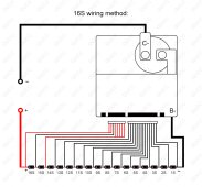
Yeah I did. It was just throwing me off that it was still showing cells 14-17 at zero. I thought it would mess with everything. But apparently that’s what it’s suppose to do. So everything is working good now!Wire the leads for 14 - 17 together and attach them to the third highest cell. In your case 14
Did you just receive one of these from Docan by chance?
That’s how I have it wired. Everything is working now. Thanks for the diagram!Is your wiring done the same way as in this attached picture?
I also have two of these, which I want to use parallel with 2 blocks of 10kWh NMC batteries.
I don't really understand why they can't go in parallel, especially with these big contactors/relays on them.
Anyway, there will be fuses between the blocks as well as a DC breaker, just to be sure.
I also struggled with the number of cells. It looks like it allows you to set the number of cells in the parameters, but it doesn't use that, it keeps using the autodetect feature.
Reading this thread together with the documentation I got it to go down to 16s, but I have 14s
So it is quite picky when it comes to the wiring, I probably really need to solder them together.
Currently I shoved them all together in one crimp connector, but it is still detecting a possible 15th and 16th cell, which aren't there, and are reading voltages of 0.1v or so.
While it is in this state, the other battery cell voltages aren't to be trusted.
So I have to do some testing on them, haven't really put them to use yet, but so far I like them.
I don't like the busbar being so naked, from the PCB to the relay. I might cover that.
slurrr
New Member
- Joined
- Feb 15, 2022
- Messages
- 8
I’m pretty sure it’s supposed to show that you only have 16 cells and not show the 0v readings…Yeah I did. It was just throwing me off that it was still showing cells 14-17 at zero. I thought it would mess with everything. But apparently that’s what it’s suppose to do. So everything is working good now!
Where did you source your bms? I got one from docan power and it has a generic looking contactor with no TE sticker or scannable code.
They are supposed to come with an IHV200 contactor but I’ve seen some people get EV200. I’m skeptical about the one I received.
Yes the cells that aren't there should go away completely (so not being present and reading 0v or so)I’m pretty sure it’s supposed to show that you only have 16 cells and not show the 0v readings…
Where did you source your bms? I got one from docan power and it has a generic looking contactor with no TE sticker or scannable code.
They are supposed to come with an IHV200 contactor but I’ve seen some people get EV200. I’m skeptical about the one I received.
I bought two at once, and one has a sticker on the contacter which is an EV200 and the other doesn't have a sticker at all.
Otherwise, they look exactly the same.
I got the cells to go away! I had 14-17 attached to the wrong cell. I just got mine from docan this week as well. Mine has the little bar code on the contactor to scan but isn’t working. Should I be worried about it? Also does anyone have recommendations on a lcd display that will work with this bms?Yes the cells that aren't there should go away completely (so not being present and reading 0v or so)
I bought two at once, and one has a sticker on the contacter which is an EV200 and the other doesn't have a sticker at all.
Otherwise, they look exactly the same.
slurrr
New Member
- Joined
- Feb 15, 2022
- Messages
- 8
Nice!I got the cells to go away! I had 14-17 attached to the wrong cell. I just got mine from docan this week as well. Mine has the little bar code on the contactor to scan but isn’t working. Should I be worried about it? Also does anyone have recommendations on a lcd display that will work with this bms?
Same with mine. I was a little worried about it but I don’t think it’s an issue. Just seemed kind of weird. They say it’s an IHV but everyone’s getting EV200 apparently. No way to even verify what you got is the only issue. Mine has the same code can’t scan.
You can google JBD screen and there’s pretty much only one that shows up and it’s like 40 bucks unless you wait from china. For that price you could buy a dedicated android device and run it as a screen. Or you can buy a shunt type battery monitor with a screen for anywhere from 20 to 100 bucks. I went with a renogy shunt monitor that comes with a screen. That way I can have two sources of information to cross check
slurrr
New Member
- Joined
- Feb 15, 2022
- Messages
- 8
Interesting. Good to know the contactors at least appear to be TEsYes the cells that aren't there should go away completely (so not being present and reading 0v or so)
I bought two at once, and one has a sticker on the contacter which is an EV200 and the other doesn't have a sticker at all.
Otherwise, they look exactly the same.
slurrr
New Member
- Joined
- Feb 15, 2022
- Messages
- 8
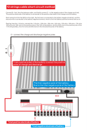
The fuse should be attached as close to your main positive as posible. It’s 400a cause the bms can handle 500 - 600a bursts according to the data sheetsBy the way, for each BMS I got a 400A fuse with it (the BMSs are the 200A version). I am unsure why it is, there is no place to mount them.
And of course I already planned to have other lower rated fuses anyway.
Yes that was what I already had made. It is probably intended as a nice extra service to include a fuse, but it seems a bit random to me without fuse holder and the fact that I might not want it so high. Oh well, will keep it for future projects.
Nica McNeil
New Member
- Joined
- Sep 30, 2020
- Messages
- 32
I was wondering the same thing about that 400 amp fuse for a 200 amp BMS. I will be using a 200 amp fuse instead.
I am getting a bit annoyed by now, I can't get the 15th and 16th cells to go away.
I have measured the resistance from the start of the balance circuit for the 14th cell up to the 20th cell, which are now all wired together, and they all read the same resistance value.
In the app I can see the 0.003v for 15th cell and 0.28v for 16th cell, which are not present on my 14s system obviously.
Another thing that worries me is that it seems to reset a bunch of settings depending on the amount of cell detection.
Maybe the limits you set stay that way, and are just multiplied by a different s number whej it automatically sets max pack voltage and so on.
In the app I cannot disable the automatic cell detection. Is this perhaps configurable through pc desktop or through another app?
Edit: Ah, I was misreading the whole thing, from the manual I now get that only the top two (red) wires should go to the highest cell positive (equal to battery positive) and the lower remaining ones should not be connected to the highest positive cell but to the second highest.
So by changing that I got it down to 15s, now it is seeing the 14th cell with 0.002v.
I'll keep on tinkering.
Last edited:
slurrr
New Member
- Joined
- Feb 15, 2022
- Messages
- 8
Read above comments. Wire all the leads you aren’t using to your THIRD highest cell, together with the lead for that cellI am getting a bit annoyed by now, I can't get the 15th and 16th cells to go away.
I have measured the resistance from the start of the balance circuit for the 14th cell up to the 20th cell, which are now all wired together, and they all read the same resistance value.
In the app I can see the 0.003v for 15th cell and 0.28v for 16th cell, which are not present on my 14s system obviously.
Another thing that worries me is that it seems to reset a bunch of settings depending on the amount of cell detection.
Maybe the limits you set stay that way, and are just multiplied by a different s number whej it automatically sets max pack voltage and so on.
In the app I cannot disable the automatic cell detection. Is this perhaps configurable through pc desktop or through another app?
Edit: Ah, I was misreading the whole thing, from the manual I now get that only the top two (red) wires should go to the highest cell positive (equal to battery positive) and the lower remaining ones should not be connected to the highest positive cell but to the second highest.
So by changing that I got it down to 15s, now it is seeing the 14th cell with 0.002v.
I'll keep on tinkering.
Yeah I saw it now, and also in the manual.Read above comments. Wire all the leads you aren’t using to your THIRD highest cell, together with the lead for that cell
The example table doesn't seem correct, but later on there is a table about automatic wiring:
14S BC12~BC18 short, All connect the 12th string of positive
pole of the battery pack
Which must mean, just like commented in this thread, that the 13th cell should go on pin 20.
Finally wired it correctly and got it running.
The settings are all pretty straightforward as usual.
Just one setting, the hardware overcurrent protection seems strange to me. It is maxed at 100A
"The hardware discharge overcurrent protection is when the front-end detection chip detects that the current is greater than the hardware discharge over-current protection value, the BMS turns off the discharge switch, stops the discharge, and the general hardware over-current value is 3-5 times of the rated current."
3 to 5 times should be 600 to 1000A for the 200A version. But it is limited to 100A which is a problem.
Unless they mean that 100A will go times 3 to 5...
But here are some of my questions about this BMS if anyone could answer I would be appreciated:
1- In the user manual is mentioned that using these BMSs in series or parallel are not allowed? Why ? because there is 900V, 500A contactor ! it is not mosfet based bms that limit you on drain sorce voltage limitation! or sharing equal current of multiple parallel mosfets for parallel connection!
I want to know if someone use it to series up to 4 x 48V , 100A pack still is not allowed to series these packs?
Ok I used this BMS parallel, 2 times a 10kWh NMC block. I didn't like it.
It might look like parallel is better with the relays but now I think it is actually worse. Because a purely MOSFET BMS is contentiously busing with monitoring and possibly limiting current. When the relay is open, it just goes.
Which is fine if they open and close at the same time. The design was as such that the corner cases (low and high voltage thresholds as well as temperature) would rarely occur.
However in real life they were not that in sync. That may have had to do with start up scenarios (inrush current to an inverter)
Anyhow, I witnessed way too much out of sync behavior resulting in balancing currents between the two 10kWh, to often.
I switched to a CAN bus system, monitoring all cells and just have one central activator for opening/closing the relays.
This was more expensive of course, but I will never waste time again trying to parallel with these kind of relay based BMS.
Every occurence of Chinese BMSs being used parallel are always mosfets I think, typically in solutions that are meant to be paralleled. (like server rack batteries etc)
So it is defenitely possible. However, not with this BMS and I have found that the cheap price is causing me to burn more hours into it. So from now on, I will only use higher grade CAN bus BMS for paralleling NMC.
Thanks for the report. I am currently building a box for a 16S2P LFP battery that will use two of these BMSs in parallel. I have wired the cells to the BMSs and run a small discharge test with a 100W light bulb as an acceptance test. The bulb drew 0.56A at 52.8VDC (~29.6W), but neither BMS showed any discharge current. I suppose that high current capacity keeps them from having fine resolution.
I do not plan to charge the cells until I have them in a fixture, so I have not put them in parallel. Each battery will have a 300A Class T fuse. I plan to control initial inrush with the 100W light bulb (a great idea that I saw on this forum). My maximum typical usage is about 75A to my inverter, so I'm hoping that the parallel batteries will play well together. Anyway, I'll give a report after I get my ducks in a row.
Well, it might work just fine. And if it was my own setup, I eould perhaps tinker along and get it right. But it was for a customer, a drive system. It just needs to work and I didnt have time anymore. Alsp there was 2 meters of wire between them. And perhaps any inrush current alreay triggered them.
I habe 125A ANL fuse on them, and am still using contactors in the same location. Just now controlled via a central system.
I habe 125A ANL fuse on them, and am still using contactors in the same location. Just now controlled via a central system.
Similar threads
- Replies
- 4
- Views
- 237
- Replies
- 8
- Views
- 653
- Replies
- 0
- Views
- 253
- Replies
- 2
- Views
- 238