diy solar

diy solar

Inverter Fundamentals...

LDVV

New Member
Joined
Feb 26, 2022
Messages
171
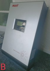
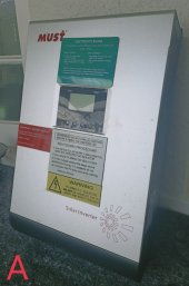
I've acquired one of these (mines actually a 2018 model, but I couldn't find a simple link!):


I got it at a bargain, so would rather take advantage of this saving and make use of it.

A few questions:

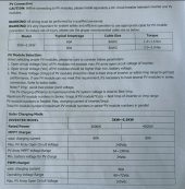
*I can't see that it's compatible with Lithium batteries. If this inverter requires that info/input, during set up, and Li is not an option, can I use an alternative selection e.g AGM (without wrecking something)?

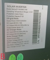
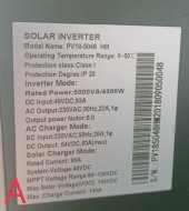
*'PV Input Power: 2880W/3840W'. My panels equal 15 X 315w = 4,725w. I can't find anywhere that I can over panel this device, but assuming I can, am I still within a safe limit?

(the PV input will be 120v @ 50A Vs the Inverter's 145v @ 60A/80A input limit)

*I'm finding myself a bit stuck for battery options, so I'd considered getting two of these: https://www.micromall.co.nz/index.p...y_id=0&sub_category=1&sort=p.price&order=DESC

Will there be any problem, connecting them in parallel, to this inverter?
 
One problem I noticed is that over-voltage kicks in at 60V? With temperature compensation, my batteries might be charging at 61V on a cool morning, and I equilize at 64V, so it doesn't even seem to be very compatical with lead-acid either?
 
One problem I noticed is that over-voltage kicks in at 60V? With temperature compensation, my batteries might be charging at 61V on a cool morning, and I equilize at 64V, so it doesn't even seem to be very compatical with lead-acid either?
I think your point is the most important to keep in mind when dealing with a PV18 platform from MUST while using an external SCC at the same time in parallel with the battery bank. I had it long ago with a 48 V lead acid battery made from 24 cells, that are important to equalize at 60 V at least once per week. During winter, due to temperature compensation, the absorption voltage of the SCC easily exceeded the 60 V and this resulted every time in the inverter going into protection mode and disconnecting the load.

To OP: Please check that your PV array open circuit voltage doesn't exceed the inverter maximum. Please calculate your PV array voltage and current (those are more important than wattage) and verify that its range match the inverter MPPT range without exceeding that.
About the battery, you can check on the inverter manual if the disconnect voltage (minimum) and floating charging voltage (maximum) can be set within the limits of the battery that you would like to buy. Apart of this also the charging and discharging current of the battery should be taken into account and compared to the inverter limitations. The PV18 has a lithium battery mode that will basically disable absorption mode, it's not that complex but that can be okay since the rack batteries you are considering got an internal BMS that will take care of the safety features.
 
I'm just looking up the parameters for Charging vs Battery now.

I've noticed in the manual that it mentions PWM and MPPT. Surely the Inverter isn't one or the other, or that I have to chose in the settings? Or it's a hybrid of both, depending on conditions and battery state?
 

Attachments

  • IMG_20220427_115944.jpg
    IMG_20220427_115944.jpg
    725.5 KB · Views: 6
In the specs for the above mentioned battery;

"Standard charging current: 100A DC"

My Array will only be making 50A.

...and the Inverter manual reads:

"Maximum utility charging current: setting range is from 1A to 60A."

(despite the label on the Inverter, and box, reading "Max charge Current: 140A", and rated current: 80A)

I'm clearly lost.

For anyone who can comprehend these specifications - are they acceptable and compatible?
 
I've noticed in the manual that it mentions PWM and MPPT.
That seems odd. Perhaps PV18 manual written with cut and paste by someone whose first language is not English?

Or that manual covers several models and poorly differentiates between them.

I dunno. Do you have pics of your PV18 so maybe someone can identify exactly what you have?
The difference that really matters is the max input voltage: 105V a bit more limiting than 145V.
 
I have two - the second is for if/when I expand.

So the only difference is that one can supply 4,000w to my AC appliances, and the other can supply 5,000w?
 

Attachments

  • IMG_20220427_130706.jpg
    IMG_20220427_130706.jpg
    275.8 KB · Views: 7
  • IMG_20220427_130648.jpg
    IMG_20220427_130648.jpg
    448.9 KB · Views: 7
  • IMG_20220427_130632.jpg
    IMG_20220427_130632.jpg
    268.8 KB · Views: 7
  • IMG_20220427_130600.jpg
    IMG_20220427_130600.jpg
    443.7 KB · Views: 7
I think the key word in this statement is "Maximum utility charging current" the word utility. I think what that means is the most current it can convert from AC into DC is 60A. The panels are putting out DC current.
 
I'm just looking up the parameters for Charging vs Battery now.

I've noticed in the manual that it mentions PWM and MPPT. Surely the Inverter isn't one or the other, or that I have to chose in the settings? Or it's a hybrid of both, depending on conditions and battery state?
Late reply but here are some more explanations to your doubts: The PV18 only comes equipped with a PWM charger or a MPPT charger. Your two units seems to be both equipped with a MPPT charger. The internal SCC is a nicely made completely autonomous board only connected to the bus bars and to the main board by a CAN cable. The SCC board can be easily replaced if damaged and swapped between PWM and MPPT.

On the label, under "solar charger mode" the "rated current" is the maximum DC current accepted from the solar array, the "max. charge current" is the maximum DC current that can be converted and provided by the internal SCC to the battery.
 
Last edited:
Late reply but here are some more explanations to your doubts: The PV18 only comes equipped with a PWM charger or a MPPT charger. Your two units seems to be both equipped with a MPPT charger. The internal SCC is a nicely made completely autonomous board only connected to the bus bars and to the main board by a CAN cable. The SCC board can be easily replaced if damaged and swapped between PWM and MPPT.

On the label, under "solar charger mode" the "rated current" is the maximum DC current accepted from the solar array, the "max. charge current" is the maximum DC current that can be converted and provided by the internal SCC to the battery.

Thanks a lot for the clarification.

I would've thought this unit would need to be grounded in some way. It seems it could be grounded via the AC Input, but this will be grid free. Any advice there?
 
Your SCC has 80A output of battery charging current from the solar panels, and 60A of battery charging current from the utility power source, thus 140A (80A + 60A total charging current for the batteries.
80A is NOT the max DC current accepted from solar array. I have MPP Solar MK that has the same spec of charging current for the batteries.
So if you do not have utility then the max battery charging current will be 80A, the MPPT SCC is basically a smart Buck converter that converts high Voltage low current from panel and down convert to battery charging Voltage with higher current.
What ever you do make sure the Voc from the panels will not exceed 145V, you also should factor in 15 ~20% headroom since the Voc will go up on cold temperature.
 
Also!

It seems the Units are identical (Model name/number etc), until you see the second part of *Rated Power*.

Given that difference, can I still run two of them, in parallel together?
 
Need to do the research to find out what the difference between VHM and HM.
The DC input current and PF are also not the same.
 
Need to do the research to find out what the difference between VHM and HM.
The DC input current and PF are also not the same.
Bad oversight there!

Luckily one was free, and the other was cheap.

I'm wondering now, if to sell them off and buy two that I can put in parallel...or a 10Kw one.
 
As a slight detour...

I see some High Voltage Inverters - consistently with a "must be installed by a qualified electrician".

Whether you're working with low voltage (like mine @ ~120v and 10A), or 200+v and 10A, if you're complacent, you're cooked anyway, right?

...and the only gain being; you get to use lower gauge power cables from Array to Inverter?

***
Before all components are installed/connected, I'll be having a Solar Installer come and "proof read" the plan anyway.
***
 
Last edited:
Back
Top