You are using an out of date browser. It may not display this or other websites correctly.
You should upgrade or use an alternative browser.
You should upgrade or use an alternative browser.
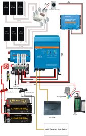
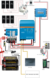
Did I Design This Correctly? 24v/10.2KWh/1200w RV system. (Diagram attached)
- Thread starter Jon22896
- Start date
eXodus
Solar Addict
- Joined
- Jul 27, 2020
- Messages
- 1,483
You are missing fuses between the panels and the combiner and charge controller.
What voltage are the panel running? Without that you can't tell if the wire to the mppt is correct.
Why do you got another ground from the inverter to the mppt?
Good start. Just a few details to flush out.
What voltage are the panel running? Without that you can't tell if the wire to the mppt is correct.
Why do you got another ground from the inverter to the mppt?
Good start. Just a few details to flush out.
FYI - It's "American Wire Gauge" - AWG.
Post the full specs of your solar panels. How long will the wire be from the combiner box to the SCC? This will help determine if 8AWG is appropriate.
What is the amp rating on your 24V->12V DC-DC converter?
You have a 100/50 SCC. That means the output current is 50A. For that you only need 6AWG wire, not 2AWG. It's like the 100/50 won't even accept 2AWG. Yep, just checked - max of 6AWG. And the 100A fuse you plan is much bigger than needed. A 65A - 70A fuse is plenty for a 50A load.
Your 3000W 24V inverter can pull up to 140A. 4/0AWG wire is much bigger than needed. You'd be fine with 0AWG. You only need a 175A fuse, not 300A. All of your 4/0AWG wires can be 1/0AWG.
Wouldn't the fuses be inside the combiner box?You are missing fuses between the panels and the combiner and charge controller.
Jon22896
New Member
- Joined
- Feb 6, 2022
- Messages
- 14
I was under the impression that if I'm running 2p I don't need to fuse the panels, but anything more than 2p fuses would be required. Is that incorrect? If I need fuses, what type size would you recommend?You are missing fuses between the panels and the combiner and charge controller.
What voltage are the panel running? Without that you can't tell if the wire to the mppt is correct.

This is something that was recommended at explorist.life. I'm not sure why, but I think it's simply because there are not enough connection points on the Lynx for the charge controller ground, so they recommended running it to the inverter then to the lynx. Do you recommend something different?Why do you got another ground from the inverter to the mppt?
Thanks so much for your comments!Good start. Just a few details to flush out.
Last edited:
OzSolar
Whatever you did, that's what you planned.
Charge Controller wire could be stepped down to #6. Even though you'll rarely if ever see the max solar panel wattage we will still use it for the calculations.
1200 watts/24v = 50 amps which is also the most your CC will put out anyway. Then replace that fuse in the LYNX with 60.
A class T fuse on the output of each battery is the typical recommendation but some will say that the BMS in the batteries make that unnecessary.
In lieu of a Class T fuse you could install an MRCB which does give you the ability to troubleshoot and isolate a bad battery thus keep your system working while you're on the road trying to enjoy yourself.
Jon22896
New Member
- Joined
- Feb 6, 2022
- Messages
- 14
Thanks for catching that typo! And all the great points.FYI - It's "American Wire Gauge" - AWG.
Just posted the full specs in my last reply. See above.Post the full specs of your solar panels. How long will the wire be from the combiner box to the SCC? This will help determine if 8AWG is appropriate.
The output is rated at 40 amp @ 12 v. This is the one I'm looking at: uxcell New BIG-Size Voltage Converter Regulator DC/DC DC 24V to DC 12V 40A 480W Buck Transformer WaterproofWhat is the amp rating on your 24V->12V DC-DC converter?
Thank you! That makes total sense.You have a 100/50 SCC. That means the output current is 50A. For that you only need 6AWG wire, not 2AWG. It's like the 100/50 won't even accept 2AWG. Yep, just checked - max of 6AWG. And the 100A fuse you plan is much bigger than needed. A 65A - 70A fuse is plenty for a 50A load.
Great! I had them all at 1/0 AWG, but then I saw this chart and upped everything to 4/0. I'll size that back down to 1/0.Your 3000W 24V inverter can pull up to 140A. 4/0AWG wire is much bigger than needed. You'd be fine with 0AWG. You only need a 175A fuse, not 300A. All of your 4/0AWG wires can be 1/0AWG.
Jon22896
New Member
- Joined
- Feb 6, 2022
- Messages
- 14
I was a bit stuck on this one. the converter output is rated for 40 amps @ 12v. Does that mean the input is approx 20 amps @ 24v? In that case, should I fuse that with, say, a 25 or 30 amp fuse?I'm guessing the pigtails on that little dc2dc converter could melt or catch fire before a 100 amp fuse would blow.
Your diagram indicates your 6 panels will be in 6P so all 6 need to be fused. If you actually meant your panels to be wired in 3S2P (which is supported by the 100/50) then you do not need any fuses or a combiner box. But it is common to have a DPST disconnect switch near the SCC. Make sure the switch/breaker is rated for the voltage of your array and that it has more amps than your array.was under the impression that if I'm running 2p I don't need to fuse the panels, but anything more than 2p fuses would be required. Is that incorrect?
One you clarify your actual panel arrangement then we can verify the details.
OK. The 40A is the 12V output. The 24V input will only be half of that (plus a tiny bit more due to inefficiencies). So assume 25A input. You only need 10AWG wire from the Lynx to the converter. And you only need a 30A fuse. 6AWG is way too big. The converter will only have 10AWG leads at best, maybe even 12AWG. For the 12V output you should use 8AWG but again, the leads won't be that big.The output is rated at 40 amp @ 12 v.
That chart seems aggressive. It claims the max inverter input amps for a 24V 3000W inverter is 200A. But 3000W / 24V / 90% = 140A.I had them all at 1/0 AWG, but then I saw this chart and upped everything to 4/0. I'll size that back down to 1/0.
Jon22896
New Member
- Joined
- Feb 6, 2022
- Messages
- 14
Yes, that was unclear. The panel arrangement will be 3s2p. I was hoping to do all of the series and parallel connecting inside the junction box so that it is easy to rearrange. I'd like to add a second SCC and a few more panels to the system down the road.Your diagram indicates your 6 panels will be in 6P so all 6 need to be fused. If you actually meant your panels to be wired in 3S2P (which is supported by the 100/50) then you do not need any fuses or a combiner box. But it is common to have a DPST disconnect switch near the SCC. Make sure the switch/breaker is rated for the voltage of your array and that it has more amps than your array.
One you clarify your actual panel arrangement then we can verify the details.
That makes sense to me. I'll make those changes now.OK. The 40A is the 12V output. The 24V input will only be half of that (plus a tiny bit more due to inefficiencies). So assume 25A input. You only need 10AWG wire from the Lynx to the converter. And you only need a 30A fuse. 6AWG is way too big. The converter will only have 10AWG leads at best, maybe even 12AWG. For the 12V output you should use 8AWG but again, the leads won't be that big.
That's what I thought too. Thank you for confirming.That chart seems aggressive. It claims the max inverter input amps for a 24V 3000W inverter is 200A. But 3000W / 24V / 90% = 140A.
Jon22896
New Member
- Joined
- Feb 6, 2022
- Messages
- 14
Thank you! This seems to be the consensus. I'll make those changes.Charge Controller wire could be stepped down to #6. Even though you'll rarely if ever see the max solar panel wattage we will still use it for the calculations.
1200 watts/24v = 50 amps which is also the most your CC will put out anyway. Then replace that fuse in the LYNX with 60.
The EG4 batteries each have their own 125 amp breaker built-in. Do you think an additional fuse is necessary?A class T fuse on the output of each battery is the typical recommendation but some will say that the BMS in the batteries make that unnecessary.
I think the built-in 125 amp breaker on each EG4 battery will also accomplish this. Right?In lieu of a Class T fuse you could install an MRCB which does give you the ability to troubleshoot and isolate a bad battery thus keep your system working while you're on the road trying to enjoy yourself.
Last edited:
John Frum
Tell me your problems
- Joined
- Nov 30, 2019
- Messages
- 15,233
What is the wire gauge and insulation rating on the in and out wires?I was a bit stuck on this one. the converter output is rated for 40 amps @ 12v. Does that mean the input is approx 20 amps @ 24v? In that case, should I fuse that with, say, a 25 or 30 amp fuse?
OzSolar
Whatever you did, that's what you planned.
It totally will!I think the built-in 125 amp breaker on each EG4 battery will also accomplish this. Right?
I have not had my hands on those specific batteries so my brain was stuck on ones that don't have built in breakers which is super nice.
There is a picture on the Amazon link the OP provided that shows 12AWG on the input and 10AWG on the output. The 10AWG should be OK as long as it's kept short.What is the wire gauge and insulation rating on the in and out wires?
Connecting the panels in the desired arrangement inside the junction box should work. With 3S2P you don't need any fuses. You will have about 75V at 20A on the output. The proper size wire depends on how long the wire will need to be from the panels/junction box to the SCC.The panel arrangement will be 3s2p. I was hoping to do all of the series and parallel connecting inside the junction box so that it is easy to rearrange. I'd like to add a second SCC and a few more panels to the system down the road.
Jon22896
New Member
- Joined
- Feb 6, 2022
- Messages
- 14
The wire might be as short as 10 ft if I drill a new hole in roof or 25 ft if I use existing refrigerator vent. I'm leaning towards 25 ft.Connecting the panels in the desired arrangement inside the junction box should work. With 3S2P you don't need any fuses. You will have about 75V at 20A on the output. The proper size wire depends on how long the wire will need to be from the panels/junction box to the SCC.
Jon22896
New Member
- Joined
- Feb 6, 2022
- Messages
- 14
The wire might be as short as 10 ft if I drill a new hole in roof or 25 ft if I use existing refrigerator vent. I'm leaning towards 25 ftConnecting the panels in the desired arrangement inside the junction box should work. With 3S2P you don't need any fuses. You will have about 75V at 20A on the output. The proper size wire depends on how long the wire will need to be from the panels/junction box to the SCC.
Similar threads
- Replies
- 2
- Views
- 234
- Replies
- 0
- Views
- 207
- Replies
- 50
- Views
- 2K
- Replies
- 4
- Views
- 196


