diy solar

diy solar

Inverter Kicking Off

Lets solve this with Ohms Law. Assume a 2 ohm load on 12.6 volts, 12.6 / 2 = 6.3 amps now same load as its not changed 10.0 volts /2 = 5 amps. Basic stuff. Less volts less amps. Watts are not constant, watts = volts x amps and if on AC x Pf. Watts are not a constant, loads are.
 
Last edited:
Except an inverter is not a regular resistive load. It is trying to make sure it pushes 120V or 240V consistently at whatever amperage is required by what's plugged in. So, if the input voltage drops, it will attempt to draw more amps to maintain its voltage and current output to the load connected to it.

Yes, when a battery is dead it cannot handle it, and the volts sag more and done. However, there is a point where the battery SoC is getting lower and the volts are dropping off somewhat, but it can still maintain the current necessary.

When doing the calculations, it is safer to do it at "worst case" so you have no ugly surprises.
 
No, an Inverter is a Constant Load. Thats it, Wattage is not a Constant, it varies as the voltage and amp draw changes. Ohms Law solved the problem for you. Amp draw depends on the example I posted 78 amps at 13 vdc, for a 1000 watt inverter.
 
Last edited:
No, an Inverter is a Constant Load. Thats it, Wattage is not a Constant, it varies as the voltage and amp draw changes. Ohms Law solved the problem for you. Amp draw depends on the example I posted 78 amps at 13 vdc, for a 1000 watt inverter.
The AC load would be considered constant, while the DC side changes

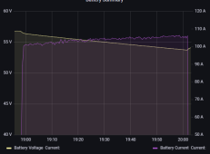
Here's a screen shot from a constant AC load, while the DC side changes
At the beginning, 56.3 volts x 101 amps = 5686 watts
At the end, 53.7 volts x 106 amps = 5692 watts

1651248961308.png
 
The AC load would be considered constant, while the DC side changes

Here's a screen shot from a constant AC load, while the DC side changes
At the beginning, 56.3 volts x 101 amps = 5686 watts
At the end, 53.7 volts x 106 amps = 5692 watts
Just out of curiosity what was the constant ac load?
 
EVSE/car charging, it was mostly a test of the EVSE and my set up. But the AC load was constant. I don't normally charge the car from the home battery.
What was the ac side load in watts?
 
Yes Those changes are a long ways from 13 to 10 volts! Its a 1000 watt inverter on 13 volts calculated load resistance is .166 do the Ohms law using that and 13 volts and 10 volts. That is at max rating of the inverter. Its current limited to not exceed the inverter rated watts.
 
What was the ac side load in watts?
5500 watts, sorry no graph.

Yes Those changes are a long ways from 13 to 10 volts! Its a 1000 watt inverter on 13 volts calculated load resistance is .166 do the Ohms law using that and 13 volts and 10 volts. That is at max rating of the inverter. Its current limited to not exceed the inverter rated watts.
I give up
 
Yes Those changes are a long ways from 13 to 10 volts! Its a 1000 watt inverter on 13 volts calculated load resistance is .166 do the Ohms law using that and 13 volts and 10 volts. That is at max rating of the inverter. Its current limited to not exceed the inverter rated watts.
/facepalm
 
I don't blame you 13 volt / .166 = 78 amps, 10 volt / .166 = 60.2 amps. I will stick with Mr. Ohm has been right for 60 years or so, he has not been wrong yet. Neither was my EE teacher.

The inverter is limited to the max amp rating so this is a incorrect statement: So, if the input voltage drops, it will attempt to draw more amps to maintain its voltage and current output to the load connected to it.
 
Last edited:
Have you measured the voltage at the inverter positive/negative terminals while it is on load? It sounds like a voltage drop condition as the battery gets low.
That is not much battery for a few hours of inverter.
The fridge has a data plate. What is the listed watts of the fridge?
The fridge is a freezer I've converted to a fridge so I think that data would be irrelevant right?

I haven't measured at the terminals when the shut off happens but it reads 13.4 at input terminals on load and the watt meter shows around 110 volts while it's running and .92 amps
 
Last edited:
The fridge is a freezer I've converted to a fridge so I think that data would be irrelevant right?

I haven't measured at the terminals when the shit off happens but it reads 13.4 at input terminals on load and the watt meter shows around 110 volts while it's running and .92 amps
How many batteries?

I would check connections on the Input side, you can have voltage but a bad or loose connection will not pass enough current. Wire size?
 
How many batteries?

I would check connections on the Input side, you can have voltage but a bad or loose connection will not pass enough current. Wire size?
One LiFePO4 battery 100 amp, wire size 4 gauge from fuse to inverter.
 
Last edited:
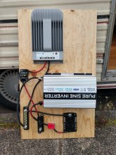
Here's a photo of the setup before wiring. (+ 2x 100 watt panels and SOK LiFePO4 100 amp battery)
This morning I turned it on to try to test the voltage when it happens but so far it has happened twice and immediately kicks back on and voltage normal- which is a new phenomenon, so I haven't been able to test the voltage when it happens.

Things I'm thinking in response to responses.

1. maybe I just need to go ahead and add a second battery and more panels (although 70 amp load still seems like a very small load to me)
2. I used hardware store lugs that weren't UL listed on a couple of the connections. they seemed cheap and thin but I needed to move into my rv that day so went ahead with them. maybe they are causing a problem.
3. Even though the 4 AWG wires to the inverter are very short maybe I should use a larger wire

I'm thinking upping the wire size at the inverter inputs and redoing all connections that had the cheap lugs or lugs that didn't fit perfectly. Some of them weren't exactly the right size but seemed they would still make a good connection. Anyone think this is a good place to start?
 

Attachments

  • 0-5.jpeg
    0-5.jpeg
    162.7 KB · Views: 15
Last edited:
Here's a photo of the setup before wiring. (+ 2x 100 watt panels and SOK LiFePO4 100 amp battery)
This morning I turned it on to try to test the voltage when it happens but so far it has happened twice and immediately kicks back on and voltage normal- which is a new phenomenon, so I haven't been able to test the voltage when it happens.

Things I'm thinking in response to responses.

1. maybe I just need to go ahead and add a second battery and more panels (although 70 amp load still seems like a very small load to me)
2. I used hardware store lugs that weren't UL listed on a couple of the connections. they seemed cheap and thin but I needed to move into my rv that day so went ahead with them. maybe they are causing a problem.
3. Even though the 4 AWG wires to the inverter are very short maybe I should use a larger wire
You have stacked lugs on the fuse.
The inverter lug should be on the bottom, then charge controller, then fuse block.
Better yet, you should have a fused busbar like this one.

I propose that you stress test your system and see if it can handle a larger load.
Some ceramic heaters have a low setting that is just under 1000 watts ac, that would be a good test.
While testing you should check for hot spots along the high current path.
 
Have you actually measured this?
Yes.
I don’t have the ‘right’ meter to record the pattern, but I’ve seen both 70+ amps on my clamp meter and the watts over 850 on my inverter readout. Briefly. The math agrees amongst the devices. Then drops (plummets?) to 100-130W and very quick creeps down to the normal 60-80W running. Running a 1012LV-MK atm and the fans come on for a second when fridge starts. The former Giandel did same.
It’s real:)
 
Last edited:
You should be taking the input wires for the Inverter directly from the battery via fuses of course. What is the rating for those bus bars in amps? Charge controller goes to the battery via fuse of course. Make no difference on how the lugs are placed on a stud as long as the terminal lugs are heavy enough for the load.
 
An inverter is a constant output
So if the load on an inverter is a 100 watt light bulb it still outputs 1000 watts? The output voltage is constant and its limited to the max amp rating from the DC side as to the total wattage out. Power is expressed as voltage x amperes x Pf (if AC) = Watts
 
Last edited:
Here's a photo of the setup before wiring. (+ 2x 100 watt panels and SOK LiFePO4 100 amp battery)
This morning I turned it on to try to test the voltage when it happens but so far it has happened twice and immediately kicks back on and voltage normal- which is a new phenomenon, so I haven't been able to test the voltage when it happens.

Things I'm thinking in response to responses.

1. maybe I just need to go ahead and add a second battery and more panels (although 70 amp load still seems like a very small load to me)
2. I used hardware store lugs that weren't UL listed on a couple of the connections. they seemed cheap and thin but I needed to move into my rv that day so went ahead with them. maybe they are causing a problem.
3. Even though the 4 AWG wires to the inverter are very short maybe I should use a larger wire

I'm thinking upping the wire size at the inverter inputs and redoing all connections that had the cheap lugs or lugs that didn't fit perfectly. Some of them weren't exactly the right size but seemed they would still make a good connection. Anyone think this is a good place to start?
Looks like your Thread was HiJacked do you want to PM me for what I posted?
 
So if the load on an inverter is a 100 watt light bulb it still outputs 1000 watts? The output voltage is constant and its limited to the max amp rating from the DC side as to the total wattage out. Power is expressed as voltage x amperes x Pf (if AC) = Watts
No.
I don’t think you are fully understanding how an inverter works. Even the cheap ones are like a voltage-controlled power supply. They’ll take 14v or 11.7V or whatever and still deliver ~120V. Something has to happen on the input side as the output is constant in regards to whatever 120V load it’s presented with, while the input is or could be whatever from 11V to 15V or 14.4V. So the input amps are variable.
That’s the unprofessional description but applicable in practice.
 
Last edited:

diy solar

diy solar
Back
Top