diy solar

diy solar

Why do DC systems not make use of grounding to the same extent as with AC

I think for RV folks, cleaning up the terms used would be good to differentiate the differences between AC and DC. Why dont they just call it live/neutral/earth(grounding) on the AC side and call it positive/negative and chassis bond on the DC.
 
  • Like
Reactions: Dzl
I think for RV folks, cleaning up the terms used would be good to differentiate the differences between AC and DC. Why dont they just call it live/neutral/earth(grounding) on the AC side and call it positive/negative and chassis bond on the DC.
The manuals for DC automotive electrical equipment typically refer to battery negative as battery negative ground, never earth ground.
I am unaware if any positive ground vehicles are still being manufactured in the world but once upon a time positive ground was commonplace, though not the majority method.
 
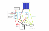
So, with all that said, for a RV system with a 48V battery bank and occasional connection to the grid through a campsite pedestal, does this look correct?

RV earthing diagram.png
 
Last edited:
So, with all that said, for a RV system with a 48V battery bank and occasional connection to the grid through a campsite pedestal, does this look correct?

When disconnected from shore power and ac fault current won't trip the breaker.
 
When disconnected from shore power and ac fault current won't trip the breaker.
So how would you connect it up then smooth joey?
I had assumed the internal components of the inverter charger would have that handled?
In a RV that is never connected to shore/grid power, how does the inverter handle a fault on the AC output side?
 
Last edited:
I am not an electrician so don't take my word for it.
When you are connected to shore power neutral and ground are bonded upstream.
When disconnected you need a neutral ground bond so that fault current can trip your breakers.
Your inverter/charger may already do this.

I would also put a surge protector between your system and the shore power.
Also you need to check that the polarity is correct and the live is live and neutral is neutral before you connect.
Some people have a "dogbone" crossover that they can put in place for this situation.
Yes thanks Joey, i have seen that with the polarity and surge protections in various vids. I'm assuming the internals of the inverter/chargers handle the 'earthing' requirements between the DC input and AC output, otherwise, how would anyones system work if never connected to grid....the breakers on the AC distribution box must have a means of tripping with such a set up.
 
Yes thanks Joey, i have seen that with the polarity and surge protections in various vids. I'm assuming the internals of the inverter/chargers handle the 'earthing' requirements between the DC input and AC output, otherwise, how would anyones system work if never connected to grid....the breakers on the AC distribution box must have a means of tripping with such a set up.

I would test that.
It will "work" without neutral ground bond but fault current may not be able to trip the breaker.
That reminds me, will you ever connect a generator to the shore power inlet?
 
I would test that.
It will "work" without neutral ground bond but fault current may not be able to trip the breaker.
That reminds me, will you ever connect a generator to the shore power inlet?
Never any generator.

I still dont quite understand why this would be. Any basic DC battery to inverter to AC distribution system on a RV, must surely be set up to allow the distribution box breakers to trip, if any cabling insulation gets breached to metal work or, if any appliances developes a fault, otherwise there are going to be a very large number of unsafe RV's out there?
 
I still dont quite understand why this would be.

My inverter generator and most in its class have a "floating neutral" even though its not intended to be connected to premises wiring.
It has a 3 prong outlet and in its normal configuration there is no neutral ground bond.
 
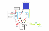
Looking at the manuals/schematics for the individual components i propose to use it would appear that this is the best way to handle earthing/grounding/bonding, despite what some others have said. (I presume the use of a 'silver' washer between the 'earth bond' busbar and the chassis would prevent corrosion?)

RV earthing diagram amended..png

The inverter/charger in particular states
"This product is a safety class I device (supplied with a ground terminal for safety purposes). Its AC input and/or output terminals must be provided with uninterruptible grounding for safety purposes. An additional grounding point bonded to the chassis is located inside the terminal cover of the product."
 
I promised Will I wouldn't get into a crap fight on the forum, but isn't there a rule against insulting users?
Doesn't that apply to 'Moderators' as well?


I have no idea where that *Claim* came from, but let someone get a video rolling before you try and 'Prove' it on some 17,000 Volt AC line, and I'll donate the rubber bath mat for you to stand on so you aren't 'Grounded'...


Almost correct.
Having built several AC generators myself, and rewinding thousands, you *Almost* have that correct, except for the the pesky details, like differentials, induction/inductance, capacitance, impedance, and a hundred other terms virtually no one understands the interactions of since they all learned from an HVAC training program, or a linemans textbook, or some other very specific training program that didn't cover what they weren't going to have to deal with on a daily basis.


Correct.
AC is a transmission because it has frequancy, throws ions, develops counter rotating magnetic fields around the conductors that spin off electro-magnetic energy 50 or 60 times a second, ect.


Patently FALSE.
I can't even begin to start on how wrong that is...
Most NATURAL forces are CONSTANT, and that's why we call them 'FUNDAMENTAL CONSTANTS'.

We can start with a free electron ALWAYS seeking a conductor and move on from there if you care to, but not in this 'Help Me' thread you participated in shredding and confusing.


And AGAIN, patently FALSE.
This is a bastardization of 'Chaos Theory' explanation, which is philosophy ('Belief') and not actual hard science or any kind of factual account of how electrical currents are produced, conducted, transmitted, ect.

And AGAIN, like mass having gravity and the electro-magnetic link, these are CONSTANTS throughout the universe.
They can be PRECISELY measured, accounted for, depended on,
A free (Negative) electron will ALWAYS seek a positively charged molecule with a free space in the outer valance shell (You call those molecules 'Conductors'), it's a constant across all elements...

Just like a MOVING magnetic field will ALWAYS INDUCE (Inductance) the extra electron out of it's valance shell to free it (you call it electrical current), it's another constant of the universe...


Incorrect, and false, but this 'Help Me Understand' thread is no place to try and expand your education, even if you were willing...
A couple of the quotes attributed to me came off your post, sorry about that... must have edited it wrong.

please don’t take my comments as insulting! I apologize if so. Your responses are very verbose is all. I try to keep an answer succinct.

I am ALWAYS willing to learn, and have a very open mind. Don’t take my responses as a close minded answer.

certainly, a 17,000 V current will jump through all kinds of matter on the way to balance... but here on he forum most diy folk are asking about the voltage range in their projects...
 
@Solarfun4jim @smoothJoey

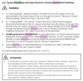
I think this excerpt from the Samlex Evo manual (pg 42) may shed some light on what you are discussing:
View attachment 8927
Which is fine, if at the time it is connected to the grid during charging mode, but if the charging power source is a SCC through the busbars, then there is no earth through the grid connection. Does this then mean, that it relies on the negative DC couplings?
I assume in that instance, it simply performs as per any non grid connected DC inverter?
 
Last edited:
There is no doubt that grounding is one of the most confusing things and source of potential weird problems if not done correctly .... The larger the system the more strange it can get. In my RV, I intend to just follow the precident already established by the manufacturer of my RV. The Samlex EVO is at the top of my list right now and I need to read that section more carefully since my RV currently doesn't have a large inverter. I will probably treat it the same as the onboard generator.

I will say that anytime there is a chance of a thunderstorm I will not have my RV connected to shore power or earth ground of any kind. The rubber tires make the possiblility of a lightning strike much less likely. Solar panels and wiring from the roof into the RV provide a path for lightning .... but if there is no earth ground .... there is no path. I also will not get in or out of my RV during a thunderstorm where I might become the earth ground.
I have had a personal experience that is the reason for my caution .... I won't bore you with that story.
 
  • Like
Reactions: Dzl
There is no doubt that grounding is one of the most confusing things and source of potential weird problems if not done correctly .... The larger the system the more strange it can get. In my RV, I intend to just follow the precident already established by the manufacturer of my RV. The Samlex EVO is at the top of my list right now and I need to read that section more carefully since my RV currently doesn't have a large inverter. I will probably treat it the same as the onboard generator.

I will say that anytime there is a chance of a thunderstorm I will not have my RV connected to shore power or earth ground of any kind. The rubber tires make the possiblility of a lightning strike much less likely. Solar panels and wiring from the roof into the RV provide a path for lightning .... but if there is no earth ground .... there is no path. I also will not get in or out of my RV during a thunderstorm where I might become the earth ground.
I have had a personal experience that is the reason for my caution .... I won't bore you with that story.
It is the single most important aspect to get 100% right first time, as just sometimes, you dont get a second chance to change your mind. Hence why i have been going on and on and on about it, boring numerous posters with it....lol.
 
It is the single most important aspect to get 100% right first time, as just sometimes, you dont get a second chance to change your mind. Hence why i have been going on and on and on about it, boring numerous posters with it....lol.
The conversation has taken a number of turns, but a lot of good information is included ..... It would make another good sticky if the good info and links were extracted.
 
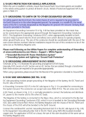
Which is fine, if at the time it is connected to the grid during charging mode, but if the charging power source is a SCC through the busbars, then there is no earth through the grid connection. Does this then mean, that it relies on the negative DC couplings?
I assume in that instance, it simply performs as per any non grid connected DC inverter?

Screenshot_20200311_135943.png
 
Oh that's easy to answer. Connect case grounds to battery negative. ABYC compliant. Add a bus bar and ground it all. Takes minutes.
  • Could that also include the ground from an SPD (per this)?
  • And you only need to add a bus bar if you've got a lot of grounds but if you've got a couple, then can go direct to the NEG bus bar, yes?
  • While you're looking at the diagram in that post, any thoughts on how to solve Shorts Scenario #1 involving PV POS wires from panels to breakers?
 

diy solar

diy solar
Back
Top