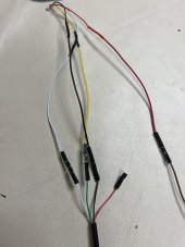
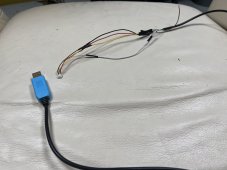
Hello I use the adapter received from JK with this one : https://www.amazon.de/gp/product/B078X5H8H7/ref=ppx_yo_dt_b_asin_title_o04_s00?ie=UTF8&psc=1What adapter do you have wired to the JK RS485 adapter? From what I can see on this page https://solar-assistant.io/shop and scroll down to Battery USB Cables and going through all of them they all seem to have the “FTDI chip” in all of them. I’m not sure how significant that is to this, but given that all of his cables have it I’m sure it means something.
If I were you I would try this one
(Industrial USB to RS485 Converter with FT232RL Embedded Protection Circuits 300-921600bps Baudrate for Industrial Control Equipments or Applications)
https://a.co/d/8oqOFuJ
I’m pretty sure the FT232RL is the “FTDI Chip”
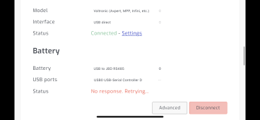
To be clear, I connected the TTL to USB adapter from the RPi directly to the BMS (no jk adapter in between)
but its not working, i will not buy anymore any adapters at all until people from sollar assistant will confirm which adapter is working 100% i have asked them several times but i have no reply. The TTL to USB adapter i haven't receive it yet waiting for it to try your option, and see if it works, with my adapter i get invalid data received for any bms i select in solar assistant.
 compared to Huck