diy solar

diy solar

EG4 6500 EX Inverter setup issues.

Oops you need 400 amps not 300.

If you want to save a bit of change get one of these

and modify according to this

Don't forget the 400 amp fuse at the battery side of the 4/0 awg feeder.
 
Follow up after trouble shooting the split phase configuration on the EG4 6500-EX inverters. During the initial inverter setup I used a single string of solar panels to power the first inverter while changing the settings, then I disconnected the panels and powered up the second inverter to perform its setup. However, when I powered each inverter with its own solar array, programmed them together, performed a shutdown and restart of the system, they both came online together. This appears to have been the issue. Both inverters are currently running split phase with no issues. Thanks for those who have their input and for all on the forum, it’s a wealth of information. Hopefully this will be helpful to anyone with this system.
Is the fault code 61 still gone?
 
The fault code 61 is gone because on inverter setting #5 I selected user instead of EG4. If you select EG4 it will be there until signature solar can come up with a fix.
 
Isn’t there a shunt in the inverters?
I doubt it.
BTW did you see this resource?
 
The fault code 61 is gone because on inverter setting #5 I selected user instead of EG4. If you select EG4 it will be there until signature solar can come up with a fix.
Sorry I missed that detail. I am following a thread on 61 and Richard said he has another.
 
FWIW with the err 61 i had this as well - the battery comm cable was going the wrong direction. If you look at the rj45 connectors the one that goes into the inverter should only have 2 wires on it. its kinda flimsy looking end but i taped mine - once i did this err 61 went away
 
Nope, but then u need to set the inverter to the generic battery like you did. They just dropped an err 61 video on youtube...
 
FWIW with the err 61 i had this as well - the battery comm cable was going the wrong direction. If you look at the rj45 connectors the one that goes into the inverter should only have 2 wires on it. its kinda flimsy looking end but i taped mine - once i did this err 61 went away
Good to know, thanks
 
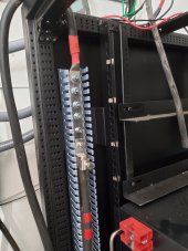
Here are the pictures of my setup. I’ve scrolled all my setting on both inverters and they both have the exact same settings except for 2P1 and 2P2.
your DC wires are far too long. I would try to keep everything from inverter to battery under 3 ft!
 
Yes it runs great. It’s pulling about 1500 watts on each inverter. My A/C will not work and I’m assuming it’s because I need to install a soft start. It’s only a 2 ton system, I figured this setup would run it no problem.
It should run no problem! Unless…you left program 28 in default phase (120*)
The screen should read for inverter L2:
28
180
2P2
Failure to do that will have definite problems for all 240volt loads yet 120 v loads would be unaffected. Under size battery lines can also cause problems with high loads. From each inverter to current interrupter 2/0 is what is recommended, however from interrupter/ common buss to battery a 4/0 for a two inverter common set of lines would be optimal(a (2/0 would be passable for 4 feet or less) if you were going to run 4 inverters you would need to double 4/0 and so on. Programming the “Voltronic” family inverters can be difficult or downright infuriating but they are a beast once it’s dialed in. Derate your loads when conditions are getting hot (95* or higher) and provide ventilation. All that difference of efficiency is going hang around as heat.
 
Same inverters and battery setup , starts my old definitely non energy star rated 2.5 ton mini split with no issues. I have the battery cables that came with the Batts as well. My batteries tie to a bus bar individually, then bus bar has 2/0 wire to each inverter, via appropriate ocpd.
So if batteries are not in there rack the 4/0 cable is not needed?. Do you have the 6ga cables that came with the batteries going to the busbar and then through a fuse breaker with 2/0 coming out of the busbar to inverters?. I'm trying to piece together everything I need for two inverters and two batteries. Do you have a picture you could share?. I have two inverters, and two batteries. Would I only need the 4/0 cables if I have 6 batteries in their rack?. Thanks.
 
Last edited:
So if batteries are not in there rack the 4/0 cable is not needed?. Do you have the 6ga cables that came with the batteries going to the busbar and then through a fuse breaker with 2/0 coming out of the busbar to inverters?. I'm trying to piece together everything I need for two inverters and two batteries. Do you have a picture you could share?. I have two inverters, and two batteries. Would I only need the 4/0 cables if I have 6 batteries in their rack?. Thanks.
The 4/0 cable requirement is a product of the total potential load. It has nothing to do with the rack itself. If you have 2 - 6500w inverters that's a potential load of 13,000 watts / 48vdc = 271 amps. This is where the 4/0 wire requirement originates. The wire must be large enough to carry the max amps the inverters could ask for.
If both inverters are fed off the same conductor from the battery bank it would need to be 4/0 and have a 400 amp t class fuse. This applies if you have a rack or not.
How are you connecting the batteries together?
Don't "daisy chain " them .

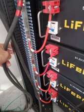
Mine has 4 batteries each individually tied to the busbar with the #6 awg cables that came with the batteries. Each inverter has a 2/0 wire that goes from the busbar neg to the inverter neg.
Each inverter has a 2/0 positive wire that goes from the positive busbar to a 200 amp dc rated circuit breaker, then into the inverter. Since each inverter has its own conductor to the battery bank we size each one to the potential of the inverter it feeds.
The large cables in the photo are the 2/0 positive wires, one goes to each inverter via a breaker.
If there was only one wire each from the bus bar positive and negative feeding both inverters it would need to sized to carry the load of both inverters so 4/0.
 

Attachments

  • 20220630_090049.jpg
    20220630_090049.jpg
    146 KB · Views: 59
  • 20220630_090010.jpg
    20220630_090010.jpg
    152.6 KB · Views: 58
So if batteries are not in there rack the 4/0 cable is not needed?. Do you have the 6ga cables that came with the batteries going to the busbar and then through a fuse breaker with 2/0 coming out of the busbar to inverters?. I'm trying to piece together everything I need for two inverters and two batteries. Do you have a picture you could share?. I have two inverters, and two batteries. Would I only need the 4/0 cables if I have 6 batteries in their rack?. Thanks.
With the distance I see in your setup, I’d be going with 4/0 between the rack and the first buss/terminal post . Find an on line and ampacity calculator. Play with cable size, distance and current and get ready for a surprise in voltage loss. Keep in mind, one volt is a TON when it comes to what the inverter sees and tries to do the right thing. A nuisance thing like back to grid early or low voltage shut down can be a problem. 95% of the normal working range of your batteries is inside a 3 volt spread. Fight voltage sag?
 
The 4/0 cable requirement is a product of the total potential load. It has nothing to do with the rack itself. If you have 2 - 6500w inverters that's a potential load of 13,000 watts / 48vdc = 271 amps. This is where the 4/0 wire requirement originates. The wire must be large enough to carry the max amps the inverters could ask for.
If both inverters are fed off the same conductor from the battery bank it would need to be 4/0 and have a 400 amp t class fuse. This applies if you have a rack or not.
How are you connecting the batteries together?
Don't "daisy chain " them .

Mine has 4 batteries each individually tied to the busbar with the #6 awg cables that came with the batteries. Each inverter has a 2/0 wire that goes from the busbar neg to the inverter neg.
Each inverter has a 2/0 positive wire that goes from the positive busbar to a 200 amp dc rated circuit breaker, then into the inverter. Since each inverter has its own conductor to the battery bank we size each one to the potential of the inverter it feeds.
The large cables in the photo are the 2/0 positive wires, one goes to each inverter via a breaker.
If there was only one wire each from the bus bar positive and negative feeding both inverters it would need to sized to carry the load of both inverters so 4/0.
What a great reply, thanks for taking the time to show me how yours is set up. Perfectly explained. I will do as you do and feed the inverters separately using the 2/0 cable and the 200A dc breakers I already have. I see you and Will did not daisy chain the batteries but I have seen a few videos where people did. I don't have a battery rack yet. Thanks for that tip as well.
 
Then I see Skypower's post. He recommends 4/0 even feeding the inverters separately?
 
.
Then I see Skypower's post. He recommends 4/0 even feeding the inverters separately?
You need to do voltage drop calculations. The voltage will fall will with increased conductor length, this will increase the amperage. As Skypower said , find an online voltage drop calculator , see what your system requires. The size of the wire is dependent on a few variables
 
.

You need to do voltage drop calculations. The voltage will fall will with increased conductor length, this will increase the amperage. As Skypower said , find an online voltage drop calculator , see what your system requires. The size of the wire is dependent on a few variables
I see a -.6v drop under a load on my 5000es when under a 40% load then goes to -.2 when load drops. I'm running 2/0 to it. The main inverter a LV5048 has a 4/0 feeding it and it's voltage doesn't sag load or not. I take my true voltage readings from the LV5048 to compare to the 5000es. BTW the 5000es powers my Mr. Cool 3 ton central Inverter A/C and the highest it draws is 47% (2350 watts) the drops down to 30% (1500 watts) pretty quick till temp is reached . When it reaches temp its 0%. It's 104 outside and the temp is set to 79 degrees with a 2 degree spread.
 
It should run no problem! Unless…you left program 28 in default phase (120*)
The screen should read for inverter L2:
28
180
2P2
Failure to do that will have definite problems for all 240volt loads yet 120 v loads would be unaffected. Under size battery lines can also cause problems with high loads. From each inverter to current interrupter 2/0 is what is recommended, however from interrupter/ common buss to battery a 4/0 for a two inverter common set of lines would be optimal(a (2/0 would be passable for 4 feet or less) if you were going to run 4 inverters you would need to double 4/0 and so on. Programming the “Voltronic” family inverters can be difficult or downright infuriating but they are a beast once it’s dialed in. Derate your loads when conditions are getting hot (95* or higher) and provide ventilation. All that difference of efficiency is going hang around as heat.

Kluoco - Did you ever get your AC going? Was this the issue? I am planning to replace my Transformer 12K Growatt with 2x EG4 6500's. I am building a home at the moment and live in a camper. I have a 13,5K BTU ac and a 15K BTU [typical 5th wheel].​


Can I expect Problems with this setup as discussed above? Will two 6500's be sufficent to keep these AC's going? If not, then I need to cancel my order? I had belived these to be sufficient for the inrush of these units.

Thank you!
 

diy solar

diy solar
Back
Top