I have a 400A service to my property (small farm, milling machine, lathe, welders, band saw)
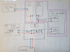
I'm trying to work up a wire diagram utilizing a 400a ATS, 2 - 12k sol-ark inverters 26KW array, and a 4kw ac coupled enphase array.
Ideally i want my solar arrays powering both of my 200A main breaker panels regardless of grid connection.
I want to leave the 4kw ac coupled array connected to 1 of the main breaker panels, i do not want to connect it to the sol-ark inverters.
The generator will be hooked up to the standby side of the ATS, but will be controlled by the Sol-Arks to charge the batteries if needed.
So the question then is where do i connect the the sol-arks to the service.
Bring the load out and grid connections from the sol-ark breakers into a bypass transfer switch. Then connect that to either the ATS terminals, or line side tap inside the ATS on the wires going to my main breaker panels?