diy solar

diy solar

Can Anyone Review My Solar Rough Draft Schematic Before Install?

acampernamedsue

New Member
Joined
Mar 25, 2020
Messages
6
Location
Austin, Texas
Hi, y'all! I'm new to the forum. I'm building a small solar system for a 1988 slide-in pop-up camper: 200W solar, 100ah battery. Attempting this with the MPP Solar 12V 800W All-in-one unit (PIP-812LV-MS). Note, I have already purchased all of my components (save a few ANL fuses). I was hoping that a few of y'all could review my "rough draft" and point out any potential issues/flaws. My biggest concerns are wire sizes & fuses; particularly the fuse to the MPP itself (considering it's a solar charger, inverter, and battery charger all-in-one). My other question is: should I wire the Master Battery Disconnect Switch between the Battery & +Busbar? Or between the +Busbar & Fuse Block? Any & all feedback very much appreciated. Cheers!

- Jeff
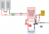
Camper_Electric_Diagram_PIC.png

MPP manual states:

MPP SOLAR GRAPH.png
 
Newbie here as well....just curious - what did you use for your 15A solar disconnect switch between the panels and inverter?

Thanks---
 
the battleborn bms will limit discharge current to 100A and will disconnect rather harshly, something you would like to avoid
i don't see the need for a 225A fuse - maybe 125-150

the wire sizes are dependent on total length i.e. pos + neg length

mark
 
So, MPP Solar's customer support emailed me recommending a 150A fuse between the PIP unit and the battery.

@mkaye - The distance from the PIP unit to the battery will be 4 feet. Will 125-150A be enough to support the load of the PIP unit (109A max rated) AND the load from the fuse box (100A max rated) coming through the busbar?
The purpose of the fuse at the battery is to protect the battery cables. I forgot how I calculated mine. But, IIRC, I think I went with 300A fuse with 4/0 6" and 9" cables for the bank at the (+) terminal post. I could of used 400A. But, no reason to worry about that until I add more inverters. 300A is more accessible. So 200A could be enough for your 2/0 if your cables are short.

I also have a circuit breaker between the battery bank and the inverter rated at 150A. I wanted 170A, but couldn't find. I could only find 150A and 200A. This is where you could base it on the inverter load, presuming the cables connecting the battery bank to the inverter are also properly rated so that the breaker needed for the inverter can be lower than required to protect the cables. Again, forgot the calculations for it, but you're looking at using at least 1.5x the inverter capacity. Even that is probably low. But, I figured, if this trips on heavy but acceptable loads, I'll get the 200A. So far, it hasn't tripped. Keep in mind that an inverter can often handle double its rating for short bursts, such as when a motor is turned on. Breakers also vary in how quickly they trip. The slower trip is to allow these short bursts. So type of load can impact which breaker you use, too. If all your loads are resistance, you can use fast tripping breakers.

My inverter is LV2424 rated for 2400w. While my memory is fading, I put lots of charts and stuff I used to figure it out here.

When you run your system, test all the wires and connections for heat under heavy load. I have yet to see them rise above room temperature in my setup.
 
Last edited:
So, MPP Solar's customer support emailed me recommending a 150A fuse between the PIP unit and the battery.

@mkaye - The distance from the PIP unit to the battery will be 4 feet. Will 125-150A be enough to support the load of the PIP unit (109A max rated) AND the load from the fuse box (100A max rated) coming through the busbar?
as i said you cannot draw more than 100A from the Battleborn (maybe more for a few seconds) as the BMS will cause a disconnect
so you can never be running the inverter at full load (assuming the 109A doesn't cause a battery disconnect) and draw any current from the DC load side i.e. the busbar will never see more than 100A
the fuse sizes are OK

using this https://www.bluesea.com/resources/1437 you can see that for your length of wire - 8' - 2awg wire can handle 120A - that is OK although i would go with 1awg - so given the comment above you would only need 120A fuse to protect the 2awg wire
 
Very well organized post and nice clear schematic. I can tell you've done your research.

My other question is: should I wire the Master Battery Disconnect Switch between the Battery & +Busbar? Or between the +Busbar & Fuse Block?

If its a 'master battery disconnect' I would wire it between the Battery+ and +Bus.

It wouldn't really be a master disconnect if you place it in between the busbar and the fuse block (that would just disconnect the battery from your 12v loads, the battery would still be connected to AC loads, Solar charging, etc.

But I suppose it depends what you are trying to achieve.

edit: one other option may be to use a 4 way switch between +Bus and MPP and 12v fuseblock, this could allow you to select, MPP only, 12V only, MPP+12V, or everything off.
 
Last edited:
The simplest & easiest fuses to use are the MRBF's and they are not expensive either.

Cheap-ish, marine rated, moderately high interrupt capacity, ABYC/USCG approved for main battery fuse on large battery banks, and such a convenient form. Also there are these combination busbar-fuseblocks which are convenient, efficient, and clean looking!

edit: also, the only fuse other than Class-T explicitly recommended by Samlex for use with their inverters--not sure about other inverter manufacturers.
 

diy solar

diy solar
Back
Top