diy solar

diy solar

5048 sunny island,150 midnite classic,300w longi panels, mndc250x2, victron bmv 700 shunt, mnpvx6 combiner

Novascotia

New Member
Joined
Oct 2, 2022
Messages
5
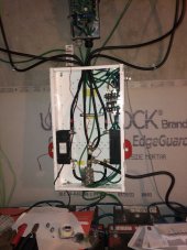
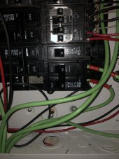
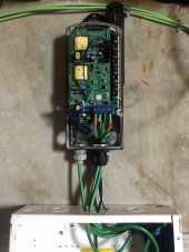
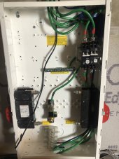
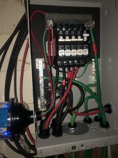
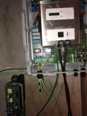
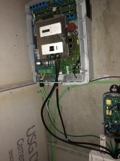
Hey everyone, have been trying to tackle a midnite/sma 48v system the last few weeks and finally all the equipment i was missing has arrived and have it almost wired just need to connect the 4/0 positive cable to the distribution block and incorporate the sma data manager and communications module, not an electrician and have only setup a simple 12v system in the past so just wondering if anyone would have time to look at the wiring and see if ive done things right a little worried to power everything up without someone who knows more than me looking it over … planned to hire a professional to do it but the two local off grid installers have told me theyve never worked with this combination of equipment before and couldn’t take on the project so have been on my own l, reading threads on here and youtube/other online sources and books have been a big help but some things are still not 100% clear due to some contradicting information thats out their so any help would be greatly appreciated thanks you!
 

Attachments

  • 2FD0134C-22EF-4898-9F3B-D907D99AEF3A.jpeg
    2FD0134C-22EF-4898-9F3B-D907D99AEF3A.jpeg
    160.4 KB · Views: 15
  • E2555342-7977-4A0B-88C8-1B2B5C808C8C.jpeg
    E2555342-7977-4A0B-88C8-1B2B5C808C8C.jpeg
    160.5 KB · Views: 15
  • D959B4BE-B6A2-45FD-96E1-705375DC3135.jpeg
    D959B4BE-B6A2-45FD-96E1-705375DC3135.jpeg
    139.7 KB · Views: 16
  • FED370DB-B26E-42EF-9FAB-6FCAD032B8C1.jpeg
    FED370DB-B26E-42EF-9FAB-6FCAD032B8C1.jpeg
    162.4 KB · Views: 15
  • F10DA68D-30E0-4113-B7BC-0DF5B63213ED.jpeg
    F10DA68D-30E0-4113-B7BC-0DF5B63213ED.jpeg
    157.1 KB · Views: 16
  • A8C4A655-3C7A-426D-ADBE-558C6A5A10E5.jpeg
    A8C4A655-3C7A-426D-ADBE-558C6A5A10E5.jpeg
    166.2 KB · Views: 14
DO NOT POWER THIS ON. At a glance it is miswired. You may damage equipment turning it on.

Your wire colors are wrong for the AC side. DC power (batteries, PV, etc) use red and black for positive and negative respectfully. AC power uses black and red as power conductors (L1 and L2), white for Neutral, and green for ground.

I think the inverter is 230v? It looks like a European 230v unit. Your main panel looks to be 120/240 split phase. This can be a problem.

I'm still digesting this... just wanted to tell you to STOP for right now.
 
Also, please confirm the frequency of your household AC and the Sunny island. If your AC is 60hz (I think it is) and the sunny island is rated for 50hz, that's not going to work.
 
Thanks Sollap appreciate your help im also worried it may damage equipment wired as it is not confident in my wiring this is just a first stab at it going off what ive been able to find for info thus far, to answer your questions my neutral ac wires coming out the inverters are marked with black tape just because I didn’t have any white they both go to the neutral bus bars on the panel, the load output wires one from each inverter go to a double 60a breaker at the bottom of the panel to backfeed, the 5048-us sunny islands each output 120 vac 60hz the previous household power from emera(Nova Scotia Power) was 120-240 60hz ive attached some drawings with labeling of how things are currently wired because in the pictures its kind of hard to tell whats wired to what
 
I'm glad to hear the inverters are 120v. I looked up the 5048 online and the first hits I got showed 230v 50hz. That definitely would have been a problem. I didn't know you had 2 inverters, I didn't pick that up in the photos at first. That explains the second red wire on your 2P breaker. I see you have a comm sync cable in your drawing so the inverters work together to provide a proper split phase 240v. All good.

You really should get some chase nipples or other connectors to protect the wires where they pass through the knockouts. The AC panel - I can already see the box digging into the insulation of the wires coming through that 1/2" knockout. It's only a matter of time before it wears through. Actually, the wires really should be in conduit, or you should be using cable assembly like NM-B. But, if you're going to just use those wires, at least protect them through the knockouts. Same for the DC wires coming out of that breaker box. It's going to be ugly if one of the hot legs gets cut into by the box.

In your drawing of the AC panel, you show the ground bar on the left and the neutral bar on the right. I don't think they are separate bars in that panel. They are connected by a small bus bar that runs under the main breaker. See those two curved aluminum bars? That's one piece I think, it runs under those bolts. You can also see the neutral conductors from other circuits going to that left side bar.

If this is a sub panel, the neutral and ground should be on separate bars. I see 4 ground bars around the perimeter of the box. Your ground wires from each inverter should go to a couple of those instead. On that subject, is that sub panel properly grounded? I don't see a ground wire going to those bars or the box. I see a green wire connecting to your neutral bar, but I assume that's acting as the panel neutral since there doesn't appear to be a wire in the larger neutral connector to the right.
 

diy solar

diy solar
Back
Top