Hi All,
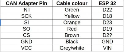
I've taken some code that handles Victron's VE.Direct protocol (Smart Shunt) and added in CAN Bus / PylonTech protocol connections, this allows the State of Charge, Voltage, Amps etc all be sent to the inverter - any one that supports the PylonTech protocol.
I have it connected to a Solis and works perfectly.
Secondly as it has MQTT I implemented commands that can be sent to enable and disable charging, and force charging, this I did so if solar isn't going to be good the following day (using Forecast Solar), then Home Assistant turns on the force charge and the inverter will charge the batteries, please note as per protocol it turns off at 97% SOC.
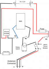
Currently I have a daly BMS on a 200amp battery pack, and a JKBMS on a 320Amp pack, tied together through the Victron Smart Shunt and it all works perfectly.
Code is here:
https://github.com/sijones/VE.DirectMQTTCANBUS


")