diy solar

diy solar

High Voltage (HV) battery from 4x 16s(48V) in series?

I don't think there is any HV compatible BMS on the market yet, from the exposure I have had to these, they use 50ah pouch cells and not traditional LFP prismatic cells, it would make them almost un-liftable in weight. I installed a Solax Triple 180v HV battery not so long ago and it looked super complicated inside.

REC supports 128s

I have SofarSolar HYD5K 20KTL-3PH inverter, that operates on 180V-800V range HV (high voltage) battery.

I consider to build HV power wall based on 4 x 48V16s batteries banks.
I haven't started yet and I am collecting all advises. What is possible, what is not? What kind of 4x BMS will be the best one for such project? Any a master BMS?

BMS have a limit what max voltage they can be series-connected for. e.g. some 12V can be connected for 48V, but not all.
Likely 48V packs do not support 96V, etc. because if they disconnect, they experience excessive voltage across their FETs.

I think adding a bypass diode (like PV panels do) would solve that limitation. It must handle full battery voltage in reverse polarity, and full current.

abandoned rental scooters are legally rubbish if they are not parked in the company space, just take them!

If I find a rental car illegally parked in my driveway, am I allowed to part it out?
 
REC supports 128s


BMS have a limit what max voltage they can be series-connected for. e.g. some 12V can be connected for 48V, but not all.
Likely 48V packs do not support 96V, etc. because if they disconnect, they experience excessive voltage across their FETs.
All the HV batteries ive been looking at seem to be using lower voltage packs, and hooking them up in series (which also makes each pack safe to work on). I really think we need to move past this HV is "dangerous" mentality, and realise its can be done safely. Im even thinking of putting an RCD (RCCB) (GFCI) on the master module of battery. This would cut the supply the second a 30ma leak was detected. Meaning a person shorting the HV leads to inverter would trip before lethal. Further more if we build using wire connectors that expose no metal, then you cant accidental short them. I made a thread specifically for HV battery safety https://diysolarforum.com/threads/high-voltage-battery-safety.51871/#post-659111

An Individual slave BMS can monitor the smaller packs, and communicate back to a master BMS which isnt exposed to the full pack voltage. This is how batrium seem to be doing it. But batriums solution is too expensive. $1705 USD. We really need to find a cost effective solution.
Found this company offering 60s for $600 USD using a slave a master setup

Lets see if we can find a better solution/deal. Im thinking 50a x 64s = 204.8v
 
Last edited:
If any one 48V BMS disconnects, I think you'll fry it. Might work if you bypass each disconnect (or use BMS that controls external one), "AND" the multiple controls, use a higher voltage disconnect.

My thinking is that bypass diode per battery solves the voltage issue.

RCD/GFCI could be a nice thing; do you have one that works for DC, and the currents involved?
Most RCD use transformers, and only detect AC imbalances. DC imbalance would saturate them (which might be a detection mechanism, though not as precise.)

REC uses master/slave above 16s, and would probably cost similar to what you say Batrium does for 60s. I think cost for 16s is around the price you show for 60s Batrium.

When building a one-off, quality and support may be worth more than unit price. Unless it busts your budget.
 
RCD/GFCI could be a nice thing; do you have one that works for DC, and the currents involved?
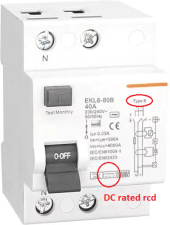
They have to be "type b" to work with DC. Ive already found some here


I think cost for 16s is around the price you show for 60s Batrium.
Both batrium and the alibaba seller are using smaller slaves to make up 60s. They just advertise its as "60s. Heres a picture of their 80s using 20s slaves
ezgif.com-gif-maker(2).jpg

If any one 48V BMS disconnects, I think you'll fry it.
I suspect the master BMS must trigger a disconnect relay for the whole battery. but im not entirely sure how it works ?
 
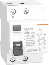
I think that says it detects and trips for both AC and DC residual currents. But is only an AC disconnect, not a DC disconnect.
It doesnt provide overload protection if thats what you mean? you would still need a fuse or DC circuit breaker for that
But it absolutely will disconnect the circuit in event of current leakage (through a human), which is the point.
 
It might detect DC leakage and open the circuit breaker.
But if it is an AC circuit breaker (I think it is, "230/240V~ 50/60 Hz"), I don't think it will successfully interrupt 200V or so DC when current is flowing. If it is supply power to a load, and a fault occurs, I think it is likely to burn, while continuing to have the leakage current (which could be a person receiving a shock.)


1670974501800.png
 
It might detect DC leakage and open the circuit breaker.
But if it is an AC circuit breaker (I think it is, "230/240V~ 50/60 Hz"), I don't think it will successfully interrupt 200V or so DC when current is flowing. If it is supply power to a load, and a fault occurs, I think it is likely to burn, while continuing to have the leakage current (which could be a person receiving a shock.)

What disconnects an RCD is different to what disconnects a circuit breaker.
The circuit breaker will break when excess amps build up. eg you short positive to negative by touching the two wires together.

An RCD trips because not because the amount of amps, but because their is an imbalance in the returning circuit because some of that current is being diverted to earth through your body and the remainder back through he wire to the battery.

I found this video useful when i was learning the concept.

Having both a circuit breaker or fuse for overload short, + an RCD for electricution would be needed.

1670974501800.png
 
I know what an RCD/GFCI is, and how it works.
I even saw one, together with its circuitry and explanation, in a display case at U.C. Berkeley (probably invented there.)

Yup:


I'm not disputing how it trips. What I'm saying is that the disconnect mechanism of the device you showed has to be able to successfully interrupt current flow. Because it is rated for AC not DC, if used with DC, it likely will not do so successfully. Plenty of videos and discussion on this forum of what happens.

Maybe if you ganged the handle of this one with a DC rated disconnect, that would achieve what you want.
Need to make sure its thresholds are low enough for intended purpose.

GFCI do exist for DC, but possibly none available with thresholds suitable for human safety.

 
Because it is rated for AC not DC,
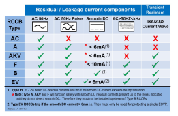
So there are differnt types of RCDs
AC only (type ac)
AC + pulsed AC (type a)
AC + pulsed DC + Smooth DC (type b)

rcd types.PNG

has to be able to successfully interrupt current flow
Yes this has to do with the breaking capacity. For example 10kA (10,000amps). If this was exceeded it wouldnt trip. The breaking capacity should be matched to the theoretical battery max amps. Seeing as most HV packs are made up of 50A cells, i would suspect 10kA would be more than sufficient.

Same is true for the cuirt breaker in event of dead short. You need a high breaking capacity. This breaker has 25kA. For comparision class T fuses that many people recommend for the high amp batteries we build, have a 20kA Interrupt Capacity.

GFCI do exist for DC, but possibly none available with thresholds suitable for human safety.
if its type b with 30ma trip, my understanding is it would be safe ?
 
Last edited:
The RCD has a test button, which creates a 30ma leak in the curcit. If the test button works & trips while connected to your battery, it would be the best way to be sure its functioning properly with DC.
 
Europe uses 30 mA whole house (maybe due to grounding different from U.S.)
US uses 5 mA for human safety.
Somewhere under 30 mA, you might be unable to let go, and GFCI doesn't trip.

Breaking capacity, AIC, the issue is short-circuit current available. Residential AC service, main breaker rated 22kA covers that. Industrial, 200kA.

Lithium batteries (and lead-acid) can put out quite a few amps.

But I'm talking about the breaker not being able to interrupt 100A, 40A, maybe even 10A. Because the source is DC, and an AC breaker relies on zero crossings to extinguish the arc.

If you mounted this device on a 200V battery and pushed the "test" button, I think it would open the circuit if no load.
If a load was drawing 20A (e.g. 4kW drawn by inverter) it might just burn and continue conducting.

You need a device rated to interrupt DC.
From the chart you gave, only "B" and "EV" are suitable for detecting and interrupting DC. Oh wait, "Residual / Leakage currents"

The link you gave does say "B", so you may be correct. Or not?
I think it detects pulsed and smooth DC, successfully tripping if above the 30 mA spec. But I am NOT convinced it then interrupts 10A at 200VDC.

The RCD has a test button, which creates a 30ma leak in the curcit. If the test button works & trips while connected to your battery, it would be the best way to be sure its functioning properly with DC.

Only if the output is loaded, say to 20A (10 ohm 4kW resistor for 200V battery).
Wear appropriate safety gear, and/or set up a mechanical arrangement to push that button remotely.
 
But I am NOT convinced it then interrupts 10A at 200VDC.
it will definitely be well worth testing on a battery under max load.

Australia is also 30ma. 5ma is much tighter. be even better if you can find one that works.
I cant imagine a situation where if a human shorted a HV battery, the leak would stay under 30ma. It would increase until it trips, almost instantaneously.
 
Last edited:
Yeah it would trip. But it wouldn't turn off. The human would continue to get cooked, along with the breaker.

Resistive short, it could stay under 30 mA. Murphy and the Better Fool will always find a way.
 
Yeah it would trip. But it wouldn't turn off
thats what is meant by trip. the RCD will thow its switch and disconnect the circuit. They couldnt be DC rating RCDs and for them not to function.
Once ive built my battery i'll be happy to run a bunch of load tests and will film & post them if you like.
 
It is NOT rated for DC.
It is rated for residual/leakage current of 30 mA.
It is rated to interrupt AC.

Do take suitable precautions when running your tests.

Take a look at @SparkyJJO avatar, for a preview of what you could be in for.
(Actually, I don't think it will be quite that bad, depending on how big a battery. But do look up the videos of AC rated and polarized DC breakers being tested with DC.)

Don't make the mistake of reading into data sheets what you would like the part to do.
And don't think that nominal tests assure safety. UL (or equivalent) listing involves some pretty severe test conditions.
 
The only way an rcd can detect leakage on a hv battery is if the battery is grounded and you have the rcd placed at the point of contact... with all grounded wiring passing through it... a hv battery is HARDLY human safe if someone is working on the battery and shorts across the terminals of the cell...
Direct paths between +&- will not be detected as a leak...
Yes you would need to ground the case (regulation here).
But if current is leaking to earth, through a person, then surely that will create a residual current imbalance that would trip at 30ma difference? (the same as if they bridged positive and negative ac)
Unfortunately i cant find anyone using an RCD on a HV battery, so maybe of course i could be completely wrong.
 
Back
Top