diy solar

diy solar

Solar house generator I started DIY back in 2000 - My path from Trace to Xantrex (on FLA battery) to XW Pro inverters on Tesla Model S batteries

2 100 ft spools from NNC $197 via PayPal shipping $29
2 100 ft spools from Platt $192 via credit card shipping $23

interesting

copper will continue to go higher, get your orders in now.....mmmmm sounds like a GOLD advertisement
 
Yeah, tell me about it!
I picked up one spool for $150 I think couple years ago? Then $250 or was it $350 to round out the rainbow.

I've also got 2 awg from 20 years back, only used maybe 25', need to pull some longer lengths. Paper spools came apart, need to transfer.

"and I need 4 colors - ouch"
Buy black wire and a set of colored phasing tape.
Four? for ground? I think it would be 8 awg minimum for ground, but of course 6 awg is fine too.

yeah, I always forget that

#8 is

$55 for 100 ft from NNC
$48 for 100 ft from Platt
 
I have my chargeverter (CV) configured (but not yet automated) to float my battery at 43.0 volts (lowest setting it will go). I have it set for 85 amps, but now drawing about 3 amps. Have had low production the past 3-4 days with overcast SOOOO I turned on the CV to run the house loads for the evening. I do wish the CV would go down to 42 or even 41 volts, which would allow me to use more of the battery. But as is, the battery is at 50% SOC and will remain there until sunny skies tomorrow (so the weather person says) will recharge the battery.

The teslas can range from 38v to 50.4v. The XW Pro gets real nervous at 40.5 so my LBCO is at 41v
I run bulk charge to 49.4v and not 50.4, to get extra life from them.

Last time I reached 49.4v was on Dec 12th

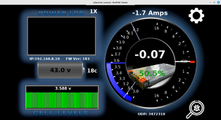
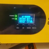
Here is pic of my status with very little battery draw (70 watts), as the CV runs the house. Battery is at 43.0 volts
I turned the CV on at 8pm, and the voltage started leveling out.


ChargeVerter floating my Tesla battery at 43.0 volts.png


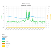
here is dec 23rd's charge graph. as it will be first evening doing this I will capture another graph from tomorrow to see how it handles it overnight

2023-12-23 charge graph.png
 
Last edited:
One of the reasons I post so much information on my project/system is that there are so many more knowledgeable than I, that can review my work and offer up improvement and corrections to my non-knowledge of some things.

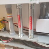
Recently @glandpuck offered up some great NEC insight on a posting I did with pictures of my installation. After some research I decided to follow his advice and am "cleaning" up some wrong PVC conduit I had done and change it to use EMT conduit.

Below are some of the conduit updates. The work is in progress, with more R&R tasks to be performed. The PVC on the left will also be replaced, but as it is composed of critical IN and OUT AC circuits I have to schedule a window of time where I can off-line the system while my wife takes a nap, lol


20231223_233228.jpg
 
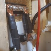
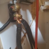
back in this post I showed some upgrades when I made my 4/0 connections from a single cable to a dual cable. In the following pics I show the final short cables that also needed doubling

20231223_233205.jpg
20231223_233158.jpg

someone asked why the double 4/0 cables. The XW Pro and PDP combo, can support 3 XW Pro inverters directly and a 4th with some external circuits. That would be 27kw of power coming from a battery which would be some 540 amps traveling between battery and the PDP. Therefore, Schneider specs for a double 4/0 connection
 
Last edited:
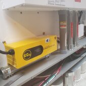
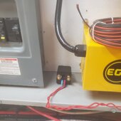
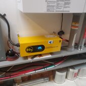
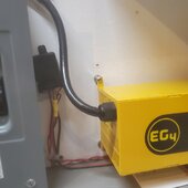
here is a pic of the 1 ChargeVerter (CV) that I currently have installed as mentioned above:

20231223_233249.jpg

I have a 2nd CV that I currently have loaned to my son. Eventually, I will get that back and will place it in parallel with the above unit. I am providing 2 NEMA L14-30 receptacles coming from my 50 amp generator input circuit. This wil allow for a generator (like my 8000 watt Winco - which can support 6300 watts at this altitude of 5500 feet, running on propane) to power the 2 CVs with some 3000 watts each, if and when needed. Also, 2 is one......

future larger generators will also be able to be utilized. Again, using CV for battery charging avoids have to use the charging function of the XW Pro and just utilize the inverter feature of the same only. In addition, using CV's reduces the use of "dirty" generator power into the inverter's charger. The Winco mentioned above is a brushless type generator and has some 20% THD or more, and thus is quite the dirty power source. The CV's can clean that and protect the inverter(s)

Lastly not having to purchase a very large generator to run the system in AC BYPASS mode and charge the battery at the same time, reduces generator costs. Even a small generator can recharge the system
 
Last edited:
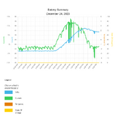
here is the charge graph for the system from midnite to now, 6PM. I turned off the CV at 11AM

voltage as flat at 43.0 volts measured at the battery, and 42.6 volts measured by the inverter via Insight

The chargeverter reports 8.7kwh consumed from the grid, to run the house from 8PM last night to now, at 7.2 cents/hr ($.59) during OFF-PEAK hours. Last time I needed the CV for low battery, I charged the battery to 47 volts while running house loads. That took 27 kw-hrs ($1.94), so I saved buying abt 20 kw-hrs of grid power ($1.32)

good sun today, 32kwh, almost filled battery

I like this "float" model for house loads better

2023-12-24 charge graph.png
 
Last edited:
work completed for Chargeverter control
RPO pending


Utilizing the XW Pro AUX Port for

  1. ChargeVerter power control and
  2. Remote Power Off (RPO) operation

this post is to document my use of 2 of the 3 functions for external control operations of the AUX port:

1) AUX Dry contactor/relay
2) Remote Power Off feature
3) External Transfer switch control

items 1 and 2 will be discussed further below

REFERENCE NOTE: related task where the AUX Port of the MPPT CC for Array #1 is used to control the HEATING of water by PV power, when the battery is FULL as pre-heated water for the house Nat Gas Tankless water heater.

Diversion of PV power when battery is full: https://diysolarforum.com/threads/s...-to-xantrex-to-xw-pro-inverters.11/post-12683
Diversion implemented: https://diysolarforum.com/threads/s...-to-xantrex-to-xw-pro-inve


The following documentation was utilized in understanding the AUX port of the XW Pro

https://download.schneider-electric...e_Name=XW-Pro-IEC-Install-Guide_990-91403.pdf

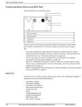
pages 53-55

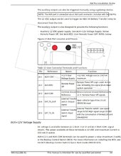
Figure 26 is looking UP at the bottom of the XW Pro. Item #3 is the AUX port, near the right front of the bottom pan

page 53.jpg

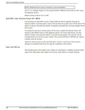
page 54.jpg

page 55.jpg

Pins JU-1, JU-2 and JU-3 of the AUX port will be wired for 2 objectives

1) JU-1 and JU-3 will be used to control 2 Solid State Relays (SSR) to turn ON and OFF the 2 Legs of GRID power connected to a NEMA L14-30r receptacle. The receptacle will allow a ChargeVerter battery charger to be enabled when the battery reaches a settable LOW Voltage level. This allows the battery to be automatically charged or simply maintained at a FLOAT voltage level. The voltage level is set by the controls of the ChargeVerter. The trigger for this control is set by parameters within the XW Pro inverter, in the AUX parameters section of the InsightLocal device.

2) JU-2 and JU-3 will used as an INPUT signal that, when the switch is CLOSED, will cause the XW Pro and Charge Controllers to shutdown. This is an earlier implementation feature of RSD (rapid shut down) technology before it appeared in the NEC regulations. The switch will be located OUTSIDE the house near the service entrance, allowing first responders to turn the solar and battery system OFF in case of fire or other event.

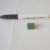
AUX Port Plugin Adapter

the following green AUX adapter plug comes in the XW Pro accessory package
it is a 5 pin adapter. as you can see, it is small header adapter

20231225_141800.jpg

20231225_141807.jpg


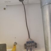
Installed AUX wire adapter and connected 5 wire thermostat cable and ran to a terminal block. took out a knock out and inserted a grommet for protection

20240122_194054.jpg

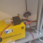
connected 2 wire to JU1 and JU3 for the 12v AUX switch and ran it to a 12v bosch relay

20240122_194103.jpg

will position the relay here, need to run a 12v line from the 12v system off to the right

20240122_194138.jpg

then will run the switched 12v wire down to the J box

20240122_194142.jpg
 
Last edited:
I will be utilizing thermostat #18/5 wire connected to the AUX pin adapter in order to exit the XW Pro box and land on a 5 position terminal block for easy access


81NPvDEgK7L._SL1500_.jpg


Once I have the terminal block on the wall and connected to the AUX port, I can tap the terminal contacts for the 2 circuits I need and run the wire to their specific locations

UPDATE: 2024-01-31

Control of LOW BATTERY Recharge with Chargeverter completed today

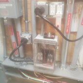
12v relay hooked up to Inverter AUX control signals
20240131_195333.jpg

240v SSR relays, plugged into grid line
chargeverter plugged to 240v relay output
240v relays primary coil wired up to 12v control
cooling fan on top of box also hookup to 12v
20240131_200541.jpg

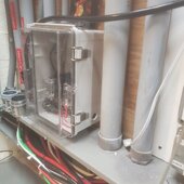
SSR relay box close up
the box has a LOCK hole where I need to place a small locking device to reduce the chance of someone opening the box and playing with the wires.
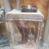
20240131_200614.jpg


Chargverter DC breaker is now ENABLED
AUX control circuit TRIGGER set to turn ON at 41.5v
LOW BATTERY CUT OUT range is 32-52v
Tesla battery (with 2 in series) depleted voltage 36v, 100% full is 50.4
I run mine 41 to 49.5v


Oprion 1 = LOW BATTERY trigger:

This option is my normal mode now, to keep the system running when we don't get as much sun as we need.
April to Oct, this trigger RARELY is activated due to the sufficient amount of sunshine we get
Nov to Mar, snow, rain, cloudy days, storms cause some days to run short of battery storage, so re-charge by grid is needed

Chargeverter voltage is set to 43.0 (the lowest it will go)
AUX control circuit CLEAR set to turn OFF at 43.5v, which will disconnect the grid
when the grid is removed from the Chargeverter, it will TURN OFF, even with the DC breaker turned on

When battery gets to low voltage, Chargeverter will turn back ON with the grid and bring the battery up to 43.0 volts.
It will then float the battery at that voltage, while running loads in the house.
This will stay in this state until the solar panels bring the battery up to 43.5v at which
time the 240v SSR relays will turn off and disable the Chargeverter, allowing the sun to do the heavy charge lifting of the battery

Option 2 = TIME OF DAY Trigger for use of TOU operation:

During Nov to Mar there are sometimes SEVERAL days in a row where the battery is depleted and no sun is forecast for several more days.
For these occurrences, the AUX port is re-configured to use TIME OF DAY operation to block out grid charging during ON PEAK times (3PM to 10PM, M-F). 10PM to 3PM is OFF peak with reduced cost per kwh.

For TOU option, I reconfigure the Chargeverter to charge the battery to 49.4 volts (1 v below the Tesla modules MAX voltage ceiling of 50.4v) and float the battery there during OFF PEAK time period

Manual configuration is needed to switch between Option 1 and Option by selecting the trigger source in the InsightLocal webpage for AUX configuration
 
Last edited:
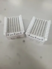
I've thought of getting a phone/LAN terminal block and punch-down tool.
I have a number of functions that can be controlled with 48V signals.
I may want to feed a particular signal to multiple places, e.g. using it to feed a relay further qualifying some control signals.
They could break out to RJ-45, making swapping easy. This would also let me remap inverters as hot spares.

1703554478624.png 1703554507793.png
 
Good progress!


You know the XW's relays are only rated at 60 amps?

I upgraded the grid breaker from 90 to 100 amp, feeding the transfer switch

I found that out that on GRID that is true 14.4kw MAX
but when in OFF grid mode (Grid breaker off - no internal AC breakers used - pure inverter output only), 2 inverters can do:

13.6kw continuous
17.0kw for 30 minute
24.0kw for 1 minute 100 amps to CLP

in inverter bypass - power from the grid, I can still draw 100 amps from the grid to power the CLP

Source:
XW Pro Multi-unit Design Guide
990-91373C
September 2022
Page 38-39 Figure 14 and Table 9
 
Last edited:
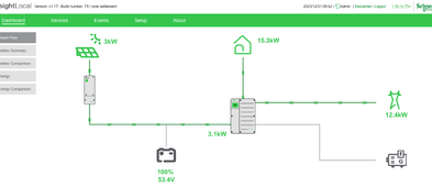
Not sure how to interpret this one.
(The well pump and resistance heat coils were both on)
Too early in the day to obtain much from the PV.

15.3kw.png
 
12.4 + 3.1 = 15.5
That's pretty close to your 15.3 kW home load.
Maybe I'm missing something, what's the question? What's to interpret?
 
I have been sick for some 4 weeks now and just this week felt good enough to do some electrical tasks in the power room

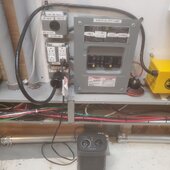
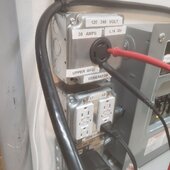
I refactored my generator service panel from 6 space to 8 space. This allows me to add a second NEMA L14-30r to power my 2nd Chargeverter (CV).

here is the panel and the 3 sets of receptacles

20240120_150331.jpg

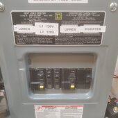
close up of the breakers
left to right:
30a LOWER L14-30
2 20a 120v
30a UPPER L14-30
60a to XW Pro Generator input

20240120_150337.jpg

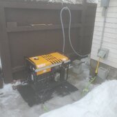
This provided me a chance to finally test the generator operation
here the generator is running on propane

20240120_150112.jpg

Here the CV is putting out about 3800 watts

20240120_150423.jpg

45 v 85 amps

20240120_150411.jpg


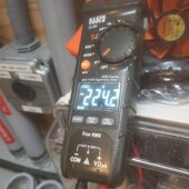
measuring the across the 2 legs

20240120_150638.jpg
 
Last edited:
the generator is outputting 224v

20240120_150611.jpg

I will explain more about that later

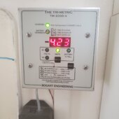
here is my meter upstairs showing wattage going into the battery 4.23kw (yeah the green button says AMPS, but that position can show AMPS or WATTS - I am in WATTS mode)
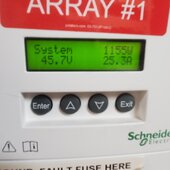
20240120_145854.jpg

in addition to the generator, the solar arrays are also generating some power under clouds of 1155 watts at this moment
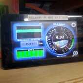
20240120_150456.jpg

and now the battery monitor display showing 4.32kw

so that is the 3825 from generator, 1155 from solar pushing 4.32kw to battery and some 700 watts to house loads

20240120_150449.jpg
 
Now as to the low voltage, I show some test results on this generator in this post above

as a brushless genset, it is using capacitance of 3 caps to generate/regulate the voltage and it is some what lacking. I did replace the old caps with 3 new OEM ones, which brought the voltage up 2-3volts to 120v at NOLOAD. They were 40uFD, but still not enough. I have a set of 3 new caps at 50uFDs and need to install and retest to see if will bring the voltage up to near 128v with NOLOAD

a task for another day
 
Last edited:
Ordered my 13th Tesla Model S battery for $540 - far cry from my first one at over $1300 4-5 years ago
I buy them one at a time, then add 2 at a time to the main battery, as I get some pennies

still, good price at around $100 per kwh

After the 14th battery (hopefully this year) I will have 70kwh of storage, on my way to 100kwh MAX
 
Back
Top