SniperX
Solar Enthusiast
- Joined
- Apr 1, 2021
- Messages
- 348
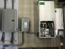
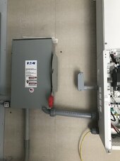
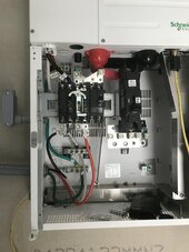
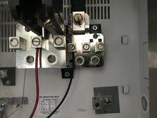
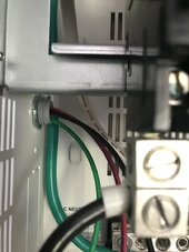
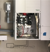
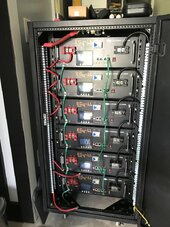
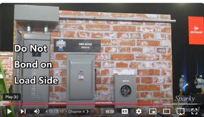
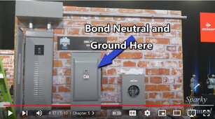
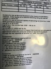
I did a little research, and wondered if you were saying to move the grounding lug over to the transfer switch because it would be on the service side of things and not on the load side (the main panel would be load and the transfer switch is before the load) In my instance, the Schneider would be on the right where the service connection would be since I am off-grid and there is no service meter. Am I understanding this correctly @wheisenburg? The third photo shows the info on the inside of the door on the transfer switch.I know it is standard industry practice to use 12-2 nonmetallic cable (better known as romex) for 240 only circuits. So you get a white and a black. Using the "correct" color isn't really an option. Running 12-3 just to have the right color is not required by code. The code may require using the correct color when using individual conductors below a certain size in a conduit.
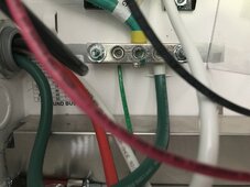
i did a little research. Apparently, reidentifying these white wires in a cable used to be optional "if the usage was obvious". Newer versions of the code now require the white wires to be reidentified. It is also true that many electricians don't do this and many inspectors don't enforce it. I think it's a good practice. Essentially on the load end where someone might think there was 120 volts on the wire.
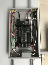
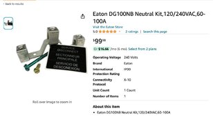
If I did that, then I would get this N-G bonding kit? https://www.amazon.com/Eaton-DG100N...ton+neutral+kit+dg100nb,industrial,103&sr=1-1
Attachments
Last edited: