diy solar

diy solar

Beginning installation of Schneider XW Pro/EG4ll batteries V1/MPPT 100A 600V OFF-GRID only questions

SniperX

Solar Enthusiast
Joined
Apr 1, 2021
Messages
348
I know these are very basic questions I should understand to even attempt to install myself, but I am in the middle of nowhere.
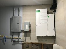
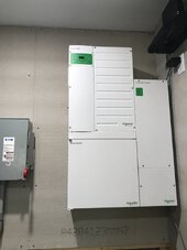
I was going to install a 12KW Growatt, but have abandoned that and purchased a Schneider XW pro, mini pdp, and their MPPT 100A 600V charge controller.

I am totally off-grid and will not have any grid-tie coming to the property.

The generator is a Honda EU7000is. (just running LED lights, a small water heater, Mitsubishi mini split, and well pump but NOT all at one time.) The generator is keeping up as long as we don't run the well pump with other things.

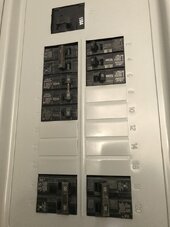
I started with a 100A main lug panel to match an Eaton 100A safety switch, but found out that I needed a breaker for the Growatt, so I switched to the 150A Main panel.

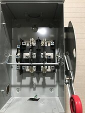
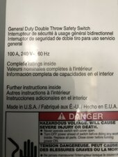
The Eaton transfer is a 100A double throw safety switch.

Now that I have the Schneider set-up listed above, my questions are:
1) The only thing on the AC side that I need to wire is the AC out to the safety switch right? I don't want the generator wired into the inverter because I won't be leaving it outside connected all the time. There is NO grid coming in. So those two places will not be wired. There are AC (grid) wires inside the pdp, so should I just wrap the ferrules in electrical tape and zip tie to something to keep them out of the way?

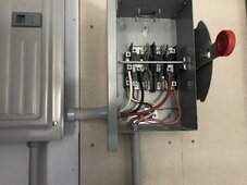
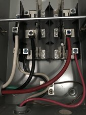
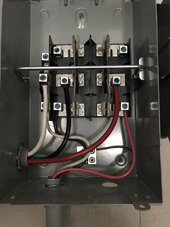
2) The inside of my transfer switch, the middle wires are #4 AWG going to the main panel and those are connected to the main lugs in the main panel. One part of the throw connects the generator, and when I switch it to the opposite side, I want it to connect to the inverter. Can I used #4 AWG to go from the transfer switch to inside the XW Pro since it is just 60A (single inverter)? The wire is 90 degree C rated.

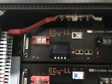
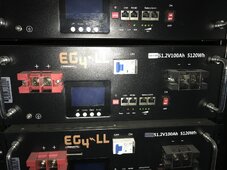
3) My battery rack is 6 EG4lls V1 100A 48Vs paralleled in their rack. I want to get a chargeverter, but I am unsure how to put this in the system. I want to run the generator (so the inverter would be in the off position on the safety switch) and the generator would be powering the main panel. Then, I would just plug the chargeverter into a wall socket and connect to the rack busbar to charge.

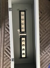
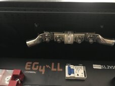
I have a 400A T-class fuse directly off the rack busbar that will then connect to a busbar in a wire chase. Should I add a 250A DC disconnect right after the T-class fuse before going to the busbar to disconnect the batteries from the inverters PV so that I can charge from the chargeverter? I was thinking redundancy but I am probably overthinking or just not getting it.

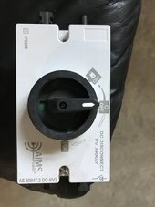
I will have a manual PV disconnect (one for each string coming in as well as a combiner box outside at the array) inside near the inverter before the PV wires go into the charge controller and also the pdp has the DC breakers there, but thought to have it closer to the battery just in case for extra precaution.

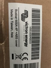
I know AC wires and DC wires either should be separated in a wire way or not be in the same wire way. I have 3 of those smaller wire ways, so I can configure the DC wires in one with the busbars. They are victron 600A 70VDC.

I appreciate all help. I'm in over my head, I know it, but I need to get off this generator.

The t-class fuse is only wired to the busbar of the battery rack right now with 4/0 wire. I have not run/connected anything yet to any other place. I am waiting on a cord from SS to update my batteries before I wire them to the rack. I was going to add some busbars inside a chase way to connect to and then go up into the inverter.
Tried to watch Dave Poz (he had a bigger pdp (not the mini) and Ben's Solar, but he is on grid and I have not been able to find anyone showing a total off-grid system like what I am describing with a safety switch instead of going into a second panel.
 

Attachments

  • 076E1864-5948-47DF-877E-90570B5B4286.jpeg
    076E1864-5948-47DF-877E-90570B5B4286.jpeg
    123.2 KB · Views: 19
  • 71AB0FA4-57AF-43CE-8894-B5BD2A480249.jpeg
    71AB0FA4-57AF-43CE-8894-B5BD2A480249.jpeg
    80.6 KB · Views: 18
  • 3F48611A-CD97-438C-BEDF-94E65227D633.jpeg
    3F48611A-CD97-438C-BEDF-94E65227D633.jpeg
    118.2 KB · Views: 16
  • 3E79410B-E0C3-4A40-BC10-2DE593150983.jpeg
    3E79410B-E0C3-4A40-BC10-2DE593150983.jpeg
    182.9 KB · Views: 15
  • 15B63815-FBD2-412E-B519-EB33D348442F.jpeg
    15B63815-FBD2-412E-B519-EB33D348442F.jpeg
    126.7 KB · Views: 15
  • 5789797E-2829-4DFC-B008-89BCC14FC4A5.jpeg
    5789797E-2829-4DFC-B008-89BCC14FC4A5.jpeg
    118.2 KB · Views: 15
  • E7A1401C-5A17-440F-881A-2B49CA65E426.jpeg
    E7A1401C-5A17-440F-881A-2B49CA65E426.jpeg
    226.5 KB · Views: 14
  • 70BECE51-3A5D-4E93-A2E2-2B1125F26FEC.jpeg
    70BECE51-3A5D-4E93-A2E2-2B1125F26FEC.jpeg
    159.1 KB · Views: 13
  • 90F8207E-B3A2-4A48-B1E3-DE84A7683AED.jpeg
    90F8207E-B3A2-4A48-B1E3-DE84A7683AED.jpeg
    106.2 KB · Views: 14
  • BCD33708-FA9A-4C95-BEDF-EDA525C74CFB.jpeg
    BCD33708-FA9A-4C95-BEDF-EDA525C74CFB.jpeg
    102 KB · Views: 17
  • 38CECE2E-E66B-4E24-AC0C-C5D7D196A04E.jpeg
    38CECE2E-E66B-4E24-AC0C-C5D7D196A04E.jpeg
    173 KB · Views: 18
  • 0E3C6448-5E8B-48A2-B214-2BD5182DAE31.jpeg
    0E3C6448-5E8B-48A2-B214-2BD5182DAE31.jpeg
    88 KB · Views: 16
  • D798DB8D-A618-46E2-A655-478A57877007.jpeg
    D798DB8D-A618-46E2-A655-478A57877007.jpeg
    184.6 KB · Views: 14
  • 7C5103AF-CC5D-4A42-B1D1-57174E7D973C.jpeg
    7C5103AF-CC5D-4A42-B1D1-57174E7D973C.jpeg
    136.2 KB · Views: 15
  • CA23A176-7C9A-47ED-9BB9-7BE0B5167D70.jpeg
    CA23A176-7C9A-47ED-9BB9-7BE0B5167D70.jpeg
    305 KB · Views: 17
I believe that you can hook the output of the chargeverter directly to the busbars, with the Honda connected to the input of the chargeverter.

See what the experts say.

You likely are aware that the Honda EU7000i has a 5,500 watt running output? It should work well with a chargeverter.

Question. What are the specs/output of you solar array?
 
1) The only thing on the AC side that I need to wire is the AC out to the safety switch right? I don't want the generator wired into the inverter because I won't be leaving it outside connected all the time. There is NO grid coming in. So those two places will not be wired. There are AC (grid) wires inside the pdp, so should I just wrap the ferrules in electrical tape and zip tie to something to keep them out of the way?
Yes, The inverter will work with AC Load connected and nothing on either AC1 or AC2 Input. However, you will not be able to use the battery charger in the inverter without an AC source. Maybe install a generator receptacle that matches the Honda. L14-30 most likely. See last comment below, is related to this subject.
2) The inside of my transfer switch, the middle wires are #4 AWG going to the main panel and those are connected to the main lugs in the main panel. One part of the throw connects the generator, and when I switch it to the opposite side, I want it to connect to the inverter. Can I used #4 AWG to go from the transfer switch to inside the XW Pro since it is just 60A (single inverter)? The wire is 90 degree C rated.
Yes, #4 is more than enough since the Inverter can only deliver 35A for 30min anyway. I'm using #6 on a 60A breaker for pass thru.
3) My battery rack is 6 EG4lls V1 100A 48Vs paralleled in their rack. I want to get a chargeverter, but I am unsure how to put this in the system. I want to run the generator (so the inverter would be in the off position on the safety switch) and the generator would be powering the main panel. Then, I would just plug the chargeverter into a wall socket and connect to the rack busbar to charge.
Yes, Although you could get more charging amps if you installed a 240V outlet for the Chargeverter.
I have a 400A T-class fuse directly off the rack busbar that will then connect to a busbar in a wire chase. Should I add a 250A DC disconnect right after the T-class fuse before going to the busbar to disconnect the batteries from the inverters PV so that I can charge from the chargeverter? I was thinking redundancy but I am probably overthinking or just not getting it.
Mini PDP already has a 250A DC battery breaker and the batteries have their own breaker. Unless you need the convenience of a single disconnect its not necessary. The Inverter can't draw more than about 250A for very brief 12kW surges. The 400A fuse is really too large to be an effective OCPD.
The t-class fuse is only wired to the busbar of the battery rack right now with 4/0 wire. I have not run/connected anything yet to any other place. I am waiting on a cord from SS to update my batteries before I wire them to the rack. I was going to add some busbars inside a chase way to connect to and then go up into the inverter.
Not following: Seems like you are trying to find ways to add unnecessary extra hardware. Why can't the mini PDP battery breaker be connected directly to the EG4 rack bus bars and fuse?
Tried to watch Dave Poz (he had a bigger pdp (not the mini) and Ben's Solar, but he is on grid and I have not been able to find anyone showing a total off-grid system like what I am describing with a safety switch instead of going into a second panel.
Again, maybe I'm not understanding the end goal. I would use the double throw safety switch in a different way. Attach the generator to the Common lugs and send one of the outputs to the Inverter Gen AC Input via the mini PDP breaker and the other safetyswitch output directly to the main breaker panel. Of course this would require another 2 pole branch breaker to be installed and interlocked with the main breaker which is fed by the inverter. This would only be feasible if there are extra spaces available in the 150A breaker panel.
 
I believe that you can hook the output of the chargeverter directly to the busbars, with the Honda connected to the input of the chargeverter.

See what the experts say.

You likely are aware that the Honda EU7000i has a 5,500 watt running output? It should work well with a chargeverter.

Question. What are the specs/output of you solar array?
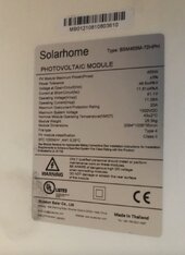
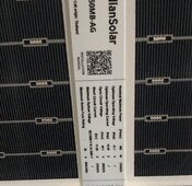
I have 11 panels at 455W and 10 panels (Canadian Solar) of 450W. I was going to put them in 4S2P when I had to work with the 250V limit from the Growatt, but have not gotten that far with the 600V of the Schneider Charge controller. I know I need to be at least over 300V and under 500V (for my comfort level) but I have not sat down to do the math yet. I have several Schneider 80A charge controllers I just came into possession of, so I can add more later. This was just to start my system. Mounting on an Iron Ridge mount. (11 panels with 1st photo specs and 10 panels with 2nd photo specs)
Totally can't believe I didn't think of putting the chargeverter on the busbar. THANKS!
 

Attachments

  • FA7AF5AF-A78D-4F44-93A6-BEB9BC76EA5D.jpeg
    FA7AF5AF-A78D-4F44-93A6-BEB9BC76EA5D.jpeg
    82.8 KB · Views: 3
  • 04C4C28E-9ABE-4B3D-BC0B-5CD542C1D1EB.jpeg
    04C4C28E-9ABE-4B3D-BC0B-5CD542C1D1EB.jpeg
    313.9 KB · Views: 3
Mini PDP already has a 250A DC battery breaker and the batteries have their own breaker. Unless you need the convenience of a single disconnect its not necessary. The Inverter can't draw more than about 250A for very brief 12kW surges. The 400A fuse is really too large to be an effective OCPD.
Throwback from when I was dealing with the Growatt which did not have those features. SS told me to use a 400A T-class fuse and I watched Dave Poz's Schneider videos and he added a 400A T-class fuse. QUICK BLOW (rather it blew then run through wires to get to a breaker somewhere up the line was my thinking. Also, Will always used T-class fuses on his setups before he started doing the newer stuff. Using 4/0 wire, so that is why I thought I would need something big since there is technically 600A in parallel. SS said that the breakers on the battery are really just shut off switches and not really DC breakers...
 
Agreed regarding the fuse, its good to have the over current protection near the source. I was suggesting the fuse be downsized so it would be more effective for the use case and sized based on the maximum current expected at the inverter. I was not suggesting the fuse be eliminated.
 
Yes, The inverter will work with AC Load connected and nothing on either AC1 or AC2 Input. However, you will not be able to use the battery charger in the inverter without an AC source. Maybe install a generator receptacle that matches the Honda. L14-30 most likely. See last comment below, is related to this subject.
Yes, I figured it wouldn't run without connecting the generator to the inverter directly. When the generator is running and the load is powered by the generator, I have outlets all over the place. I have not really looked at the chargeverter connections, but I went over to SS to see it, and yes, I will need a generator plug for the one end. I have seen pictures of it plugged in, but never investigated the cord end. Glad you mentioned that. I am a total newbie.
 
Agreed regarding the fuse, its good to have the over current protection near the source. I was suggesting the fuse be downsized so it would be more effective for the use case and sized based on the maximum current expected at the inverter. I was not suggesting the fuse be eliminated.
250A would be better or 300A? Sorry- trying to get my right-side brain over into the left side to understand the technical stuff.
 
Yes, #4 is more than enough since the Inverter can only deliver 35A for 30min anyway. I'm using #6 on a 60A breaker for pass thru.
When you say"60A breaker for pass thru" do you mean you have a 60A breaker on your main panel that when flipped on goes to a second (crucial loads or whatever you determine you want on that panel) to power the loads? Or, is the other way around, where the inverter is wired to the 60A breaker in a second panel, and that whole panel is then wired to the main panel?
 
Mini PDP already has a 250A DC battery breaker and the batteries have their own breaker. Unless you need the convenience of a single disconnect its not necessary.
Was thinking if I needed to move the batteries to work more efficiently in the space, I could do that without a lot of fuss.
 
Again, maybe I'm not understanding the end goal. I would use the double throw safety switch in a different way. Attach the generator to the Common lugs and send one of the outputs to the Inverter Gen AC Input via the mini PDP breaker and the other safetyswitch output directly to the main breaker panel. Of course this would require another 2 pole branch breaker to be installed and interlocked with the main breaker which is fed by the inverter. This would only be feasible if there are extra spaces available in the 150A breaker panel.
I have a lot of space. I went and bought a panel with way more spaces than I would ever need (for future). I wired it that way because an electrician friend of mine told me to but he said he does not understand DC at all (solar and all of it).
I see what you are saying about the generator being wired as the common (middle bar of the switch). Wouldn't that require the generator to be running all the time then if it was the common or is that what the interlock thing will determine? I either want to be on battery/solar or generator. I might be getting confused, and if so, I apologize. I know the inverter has the interlock, but am still trying to do this archaically it sounds like.
 
1) The inverter will work just fine with batteries only. The generator doesn't have to be connected to the inverter BUT then you loose the utility of the built in charger.
2) I would go with a 250A fuse.
3) Never mind, don't mean to confuse the issue. I'm actually backing up my whole house, 100A main panel via a 60A double pole breaker that feeds into the XW+ and then into the main panel. I was simply saying that #4 wire is plenty large for your application and even the smaller #6 would still be OK.
 
I see what you are saying about the generator being wired as the common (middle bar of the switch). Wouldn't that require the generator to be running all the time then if it was the common or is that what the interlock thing will determine? I either want to be on battery/solar or generator. I might be getting confused, and if so, I apologize. I know the inverter has the interlock, but am still trying to do this archaically it sounds like.

No, not at all, gen doesn't have to run except if the batteries get to low to service the load. The XW Pro has built in transfer relays on both AC 1 and AC 2 Inputs and it has to qualify the electrical source before it connects to it. By convention, AC 1 is for grid and AC 2 is for a generator.

There doesn't have to be any power applied to either of these AC inputs in order for the inverter to use battery power to convert DC to AC and supply it to the AC Load terminals. This is a typical condition when there is a grid outage, no power is supplied to the input terminals and the inverter kicks in and picks up the load. The transfer relay opens per anti-islanding requirements.
 
In the generator connection method I suggested there would be an interlock mechanism on the 150A main panel so the Main breaker and the Generator feed-in breaker could not be on at the same time.
 
In the generator connection method I suggested there would be an interlock mechanism on the 150A main panel so the Main breaker and the Generator feed-in breaker could not be on at the same time.
Thanks for the explanation and for all your time. You are awesome! I will go investigate the interlock thing and re-think my plan. I do have a 250A T-class fuse, so I will change that out for sure. I bought this system because the Growatt was too complicated and not dependable per other owners, but I guess I was afraid to use the Schneider like it was built for based off what I know about the Growatt. I will come back tomorrow with a new drawn up plan if you don't mind stopping back and checking my work. I really, really appreciate your time and expertise!
 
I think BentlyJ already covered this stuff, but I'll throw in my 2¢

1) The only thing on the AC side that I need to wire is the AC out to the safety switch right? I don't want the generator wired into the inverter because I won't be leaving it outside connected all the time. There is NO grid coming in. So those two places will not be wired. There are AC (grid) wires inside the pdp, so should I just wrap the ferrules in electrical tape and zip tie to something to keep them out of the way?
I'd either cut the zip ties and remove them or connect all the included wires. The ends are labeled and they won't hurt anything to install.
3) My battery rack is 6 EG4lls V1 100A 48Vs paralleled in their rack. I want to get a chargeverter, but I am unsure how to put this in the system. I want to run the generator (so the inverter would be in the off position on the safety switch) and the generator would be powering the main panel. Then, I would just plug the chargeverter into a wall socket and connect to the rack busbar to charge.
You already own a 150 (?) amp battery charger in the XW and a nice inverter generator. These should play nicely together. I'd wire AC2 (generator input) to a 240 plug for the generator, or hardwired if that suits your application.

The XW has generator support features that will monitor the generator output and adjust the charge current based on your AC loads to avoid overloading the generator if someone kicks on another AC load.

If you already have the manual transfer switch, I'd probably install it, but the XW includes an automatic transfer switch and the PDP includes breakers (with lockouts) that function as a manual transfer switch.
 
I have 11 panels at 455W and 10 panels (Canadian Solar) of 450W. I was going to put them in 4S2P when I had to work with the 250V limit from the Growatt, but have not gotten that far with the 600V of the Schneider Charge controller. I know I need to be at least over 300V and under 500V (for my comfort level) but I have not sat down to do the math yet. I have several Schneider 80A charge controllers I just came into possession of, so I can add more later. This was just to start my system. Mounting on an Iron Ridge mount. (11 panels with 1st photo specs and 10 panels with 2nd photo specs)
Totally can't believe I didn't think of putting the chargeverter on the busbar. THANKS!
Sniper. From your photos and comments it looks like you are doing a top notch job.

A couple of things and a question.

A quick comment; I am not an expert. I do have a Schneider XW+ set up with Discover AES batteries. My system is set up as closed loop.

Question. Is your array ground mounted or roof mounted?

1. With what you have a 10S2P, using a combiner box at the array will work well.

Then to a DC PV disconnect. I used Square D. Then to the Schneider gear.

With the specs of your modules and 10S2P you’ll be pushing just shy of 24 amps with just shy of 500 volts. Easily done with your Schneider gear.

With the Schneider gear and more modules you could go 11S2P or even 12S2P, depending on how cold it gets where you are.

2. I worked with an off-grid solar consultant who frequents the NAZ solar forum. He charges a fee for his advice. Well worth it.

He only works with top tier equipment and might only work with Schneider gear at this time.

Dave’s advice always starts with: “Read and study the documentation. Read and study the wiring diagram. Did you tighten everything to spec using a torque device?” Then he asks that you present YOUR solution to him for critique. If you are a willing and handy DIYer you’ll work well with him.

This stuff is much simpler than it appears. Start with understanding the specs of your gear. Design your solar array from those specs, then work downstream from there.

Make your process linear. First thing, second thing, etc.

Understand and implement sufficient grounding. Same with voltage drop and wire size. Use high quality SPD’s at the array(s), SPD at the solar gear as well as at your AC panel(s). I use Midnite SPD’s. Torque everything using reliable torque equipment.

The consultants advice on AGS is to not use it. Dave gets called in as expert witness by insurance companies on house fires where solar is used. He says that unattended generators are often the culprit, along with loose connections, and faulty wiring practices.

Best.
 
You already own a 150 (?) amp battery charger in the XW and a nice inverter generator. These should play nicely together. I'd wire AC2 (generator input) to a 240 plug for the generator, or hardwired if that suits your application.
140A
The XW has generator support features that will monitor the generator output and adjust the charge current based on your AC loads to avoid overloading the generator if someone kicks on another AC load.
Good point, Although I've found through limited testing that Gen Support works, but does not react fast enough to prevent large surges from momentarily drawing the voltage down on the generator causing a disconnect then a reconnect when voltage recovers and the inverter re-qualifies.
If you already have the manual transfer switch, I'd probably install it, but the XW includes an automatic transfer switch and the PDP includes breakers (with lockouts) that function as a manual transfer switch.
Funny how things come in groups. We just discussed this bypass setup related to a full sized PDP in a different post. I didn't mention this issue for 2 reasons.
1) The mini PDP is mounted below the Inverter not next to it so from a service prospective I can see removing the Inverter and PDP as a single unit. The utility of the internal, interlocked 3 breaker bypass arrangement in the mini PDP is not necessarily helpful and there is already a double throw safety switch available.
2) Trying to keep it simple and didn't want to blast out too much info all at once. We are still in the learning curve portion of the project.
 
140A

Good point, Although I've found through limited testing that Gen Support works, but does not react fast enough to prevent large surges from momentarily drawing the voltage down on the generator causing a disconnect then a reconnect when voltage recovers and the inverter re-qualifies.

Funny how things come in groups. We just discussed this bypass setup related to a full sized PDP in a different post. I didn't mention this issue for 2 reasons.
1) The mini PDP is mounted below the Inverter not next to it so from a service prospective I can see removing the Inverter and PDP as a single unit. The utility of the internal, interlocked 3 breaker bypass arrangement in the mini PDP is not necessarily helpful and there is already a double throw safety switch available.
2) Trying to keep it simple and didn't want to blast out too much info all at once. We are still in the learning curve portion of the project.
Can you link that discussion here? I came into a trove of Schneiders which I will be installing in my new house build whenever I can find a builder. It will come in handy!
 
I think BentlyJ already covered this stuff, but I'll throw in my 2¢


I'd either cut the zip ties and remove them or connect all the included wires. The ends are labeled and they won't hurt anything to install.

You already own a 150 (?) amp battery charger in the XW and a nice inverter generator. These should play nicely together. I'd wire AC2 (generator input) to a 240 plug for the generator, or hardwired if that suits your application.

The XW has generator support features that will monitor the generator output and adjust the charge current based on your AC loads to avoid overloading the generator if someone kicks on another AC load.

If you already have the manual transfer switch, I'd probably install it, but the XW includes an automatic transfer switch and the PDP includes breakers (with lockouts) that function as a manual transfer switch.
I was thinking I could put the ferrules up in their proper locations as long as I don't connect wires going out to anything. I don't want to cut them or remove them in case my set-up changes, but thanks for confirming that it is ok to do this.
I can add a plug for the generator. I was trying to avoid another hole in my wall thinking I had one installed for the generator to begin with along with the transfer switch/electrical box, but I was going to read up on it this morning. Still have PTSD from that Growatt (I spent 9 months researching it and my brain is hardwired for that info- SS saying NOT to use the Growatt for generator charging) I do have the manual transfer switch already installed.
 
Back
Top