SniperX
Solar Enthusiast
- Joined
- Apr 1, 2021
- Messages
- 359
I know these are very basic questions I should understand to even attempt to install myself, but I am in the middle of nowhere.
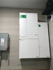
I was going to install a 12KW Growatt, but have abandoned that and purchased a Schneider XW pro, mini pdp, and their MPPT 100A 600V charge controller.
I am totally off-grid and will not have any grid-tie coming to the property.
The generator is a Honda EU7000is. (just running LED lights, a small water heater, Mitsubishi mini split, and well pump but NOT all at one time.) The generator is keeping up as long as we don't run the well pump with other things.
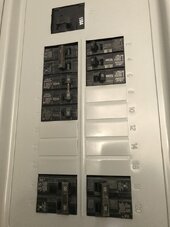
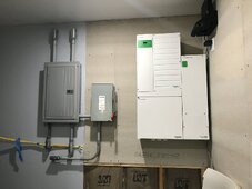
I started with a 100A main lug panel to match an Eaton 100A safety switch, but found out that I needed a breaker for the Growatt, so I switched to the 150A Main panel.
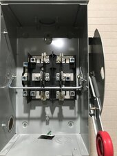
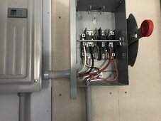
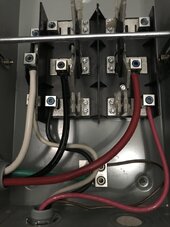
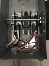
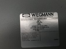
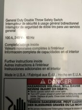
The Eaton transfer is a 100A double throw safety switch.
Now that I have the Schneider set-up listed above, my questions are:
1) The only thing on the AC side that I need to wire is the AC out to the safety switch right? I don't want the generator wired into the inverter because I won't be leaving it outside connected all the time. There is NO grid coming in. So those two places will not be wired. There are AC (grid) wires inside the pdp, so should I just wrap the ferrules in electrical tape and zip tie to something to keep them out of the way?
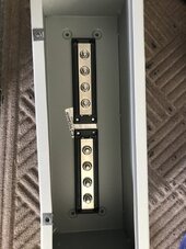
2) The inside of my transfer switch, the middle wires are #4 AWG going to the main panel and those are connected to the main lugs in the main panel. One part of the throw connects the generator, and when I switch it to the opposite side, I want it to connect to the inverter. Can I used #4 AWG to go from the transfer switch to inside the XW Pro since it is just 60A (single inverter)? The wire is 90 degree C rated.
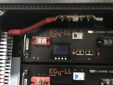
3) My battery rack is 6 EG4lls V1 100A 48Vs paralleled in their rack. I want to get a chargeverter, but I am unsure how to put this in the system. I want to run the generator (so the inverter would be in the off position on the safety switch) and the generator would be powering the main panel. Then, I would just plug the chargeverter into a wall socket and connect to the rack busbar to charge.
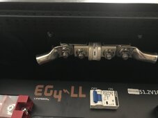
I have a 400A T-class fuse directly off the rack busbar that will then connect to a busbar in a wire chase. Should I add a 250A DC disconnect right after the T-class fuse before going to the busbar to disconnect the batteries from the inverters PV so that I can charge from the chargeverter? I was thinking redundancy but I am probably overthinking or just not getting it.
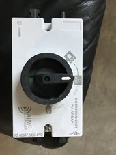
I will have a manual PV disconnect (one for each string coming in as well as a combiner box outside at the array) inside near the inverter before the PV wires go into the charge controller and also the pdp has the DC breakers there, but thought to have it closer to the battery just in case for extra precaution.
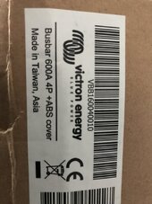
I know AC wires and DC wires either should be separated in a wire way or not be in the same wire way. I have 3 of those smaller wire ways, so I can configure the DC wires in one with the busbars. They are victron 600A 70VDC.
I appreciate all help. I'm in over my head, I know it, but I need to get off this generator.
The t-class fuse is only wired to the busbar of the battery rack right now with 4/0 wire. I have not run/connected anything yet to any other place. I am waiting on a cord from SS to update my batteries before I wire them to the rack. I was going to add some busbars inside a chase way to connect to and then go up into the inverter.
Tried to watch Dave Poz (he had a bigger pdp (not the mini) and Ben's Solar, but he is on grid and I have not been able to find anyone showing a total off-grid system like what I am describing with a safety switch instead of going into a second panel.
I was going to install a 12KW Growatt, but have abandoned that and purchased a Schneider XW pro, mini pdp, and their MPPT 100A 600V charge controller.
I am totally off-grid and will not have any grid-tie coming to the property.
The generator is a Honda EU7000is. (just running LED lights, a small water heater, Mitsubishi mini split, and well pump but NOT all at one time.) The generator is keeping up as long as we don't run the well pump with other things.
I started with a 100A main lug panel to match an Eaton 100A safety switch, but found out that I needed a breaker for the Growatt, so I switched to the 150A Main panel.
The Eaton transfer is a 100A double throw safety switch.
Now that I have the Schneider set-up listed above, my questions are:
1) The only thing on the AC side that I need to wire is the AC out to the safety switch right? I don't want the generator wired into the inverter because I won't be leaving it outside connected all the time. There is NO grid coming in. So those two places will not be wired. There are AC (grid) wires inside the pdp, so should I just wrap the ferrules in electrical tape and zip tie to something to keep them out of the way?
2) The inside of my transfer switch, the middle wires are #4 AWG going to the main panel and those are connected to the main lugs in the main panel. One part of the throw connects the generator, and when I switch it to the opposite side, I want it to connect to the inverter. Can I used #4 AWG to go from the transfer switch to inside the XW Pro since it is just 60A (single inverter)? The wire is 90 degree C rated.
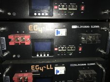
3) My battery rack is 6 EG4lls V1 100A 48Vs paralleled in their rack. I want to get a chargeverter, but I am unsure how to put this in the system. I want to run the generator (so the inverter would be in the off position on the safety switch) and the generator would be powering the main panel. Then, I would just plug the chargeverter into a wall socket and connect to the rack busbar to charge.
I have a 400A T-class fuse directly off the rack busbar that will then connect to a busbar in a wire chase. Should I add a 250A DC disconnect right after the T-class fuse before going to the busbar to disconnect the batteries from the inverters PV so that I can charge from the chargeverter? I was thinking redundancy but I am probably overthinking or just not getting it.
I will have a manual PV disconnect (one for each string coming in as well as a combiner box outside at the array) inside near the inverter before the PV wires go into the charge controller and also the pdp has the DC breakers there, but thought to have it closer to the battery just in case for extra precaution.
I know AC wires and DC wires either should be separated in a wire way or not be in the same wire way. I have 3 of those smaller wire ways, so I can configure the DC wires in one with the busbars. They are victron 600A 70VDC.
I appreciate all help. I'm in over my head, I know it, but I need to get off this generator.
The t-class fuse is only wired to the busbar of the battery rack right now with 4/0 wire. I have not run/connected anything yet to any other place. I am waiting on a cord from SS to update my batteries before I wire them to the rack. I was going to add some busbars inside a chase way to connect to and then go up into the inverter.
Tried to watch Dave Poz (he had a bigger pdp (not the mini) and Ben's Solar, but he is on grid and I have not been able to find anyone showing a total off-grid system like what I am describing with a safety switch instead of going into a second panel.
Attachments
-
 076E1864-5948-47DF-877E-90570B5B4286.jpeg123.2 KB · Views: 19
 -
 71AB0FA4-57AF-43CE-8894-B5BD2A480249.jpeg80.6 KB · Views: 18
 -
 3F48611A-CD97-438C-BEDF-94E65227D633.jpeg118.2 KB · Views: 16
 -
 3E79410B-E0C3-4A40-BC10-2DE593150983.jpeg182.9 KB · Views: 15
 -
 15B63815-FBD2-412E-B519-EB33D348442F.jpeg126.7 KB · Views: 15
 -
 5789797E-2829-4DFC-B008-89BCC14FC4A5.jpeg118.2 KB · Views: 15
 -
 E7A1401C-5A17-440F-881A-2B49CA65E426.jpeg226.5 KB · Views: 14
 -
 70BECE51-3A5D-4E93-A2E2-2B1125F26FEC.jpeg159.1 KB · Views: 13
 -
 90F8207E-B3A2-4A48-B1E3-DE84A7683AED.jpeg106.2 KB · Views: 14
 -
 BCD33708-FA9A-4C95-BEDF-EDA525C74CFB.jpeg102 KB · Views: 17
 -
 38CECE2E-E66B-4E24-AC0C-C5D7D196A04E.jpeg173 KB · Views: 18
 -
 0E3C6448-5E8B-48A2-B214-2BD5182DAE31.jpeg88 KB · Views: 16
 -
 D798DB8D-A618-46E2-A655-478A57877007.jpeg184.6 KB · Views: 14
 -
 7C5103AF-CC5D-4A42-B1D1-57174E7D973C.jpeg136.2 KB · Views: 15
 -
 CA23A176-7C9A-47ED-9BB9-7BE0B5167D70.jpeg305 KB · Views: 17