diy solar

diy solar

Beginning installation of Schneider XW Pro/EG4ll batteries V1/MPPT 100A 600V OFF-GRID only questions

You've got some nice generators, I'm jealous, really want a Kubota GL-7000 but our power doesn't go out often enough to justify the cost. Also, at 500 pounds, is not exactly portable.

The most discussed issue with the XW Pro lately on the forum has been the Enhanced Grid Support feature with regard to Grid Sell. Being off-grid this is not relevant to your use case. To put your mind at ease should you wish to use your larger system in a grid-tied manner, there is a solution. Lets save that for later, sounds like you have enough to do now.

As far as I know the issues with parallel configurations is limited to the Smaller SW series of inverters. The XW Pro should be OK as long one unit is set to Primary and the others are set to Secondary and each one has a unique unit ID number.

EDIT: Multi-unit configurations require AC sync communication cables. See Multi unit design guide 990-91373C.
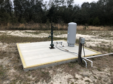
I know those big generators are not very portable- which is why I like them. No one is going to drive up and take it. Came from Va where people would leave a cheap lawn mower running at night while they took your generator during hurricanes and you would never figure it out while you were sleeping. This way, I can run the whole house if something were to happen long term (as long as I had my diesel tank full and can pump diesel when I need it) without worrying it could "walk away" easily. Also figured we might have to build our own place even though I don't want to because of lack of builders in our area. We got nailed with the last hurricane (CAT 3) and everyone was complaining about not having power and I was like, "This is everyday life for me." They could not even get water because they could not use their well pump without electricity. I had a big ole hand pump installed just for that scenario!
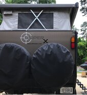
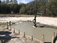
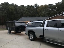
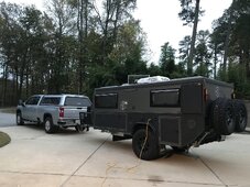
The reason I have the handle "SniperX". Australian made camper. Only one in the country that is this size and design. Runs solely on 12V/solar. (added some 110 AC to it for battery charging) Had to learn solar to learn how to understand the system. I changed the batteries to 2 parallel 12v SOK lithium 206Ah batteries, had a REDARC 1240 charge controller and added busbars, cut-off switches and better wiring so I could sleep at night without worrying it would go up in flames. 400W solar on top. Added Anderson plug so I could add 2 cig solar panels for ground mount because flat panels don't work well in the winter, lol. That journey put me onto 48V system for off-grid house. Getting ready to build a 12x12 shed over the well/pump so we can set up water filters. Live in the big bend of FL, so we do get frosts...
 

Attachments

  • FCC69567-794E-4435-ABE8-E5D0A3F6AEFE.jpeg
    FCC69567-794E-4435-ABE8-E5D0A3F6AEFE.jpeg
    151.9 KB · Views: 8
  • tempImage86k5fQ.png
    tempImage86k5fQ.png
    2.9 MB · Views: 8
  • EA1D0D9B-CAF5-4409-A451-626798D26592.jpeg
    EA1D0D9B-CAF5-4409-A451-626798D26592.jpeg
    186.3 KB · Views: 7
  • 40CA47A8-C58B-4E9C-8650-27E27EE7026F.jpeg
    40CA47A8-C58B-4E9C-8650-27E27EE7026F.jpeg
    478 KB · Views: 7
  • 6E039347-8B07-406C-BFA1-683A295CEC56.jpeg
    6E039347-8B07-406C-BFA1-683A295CEC56.jpeg
    176.3 KB · Views: 7
  • 4F47E7B6-D834-40D1-A178-045F94BE5BFD.jpeg
    4F47E7B6-D834-40D1-A178-045F94BE5BFD.jpeg
    242.7 KB · Views: 7
  • 8CBFCB34-E278-4859-A3F6-56113A165206.jpeg
    8CBFCB34-E278-4859-A3F6-56113A165206.jpeg
    371 KB · Views: 6
  • 322D73E8-8053-4E09-878E-0CA704F09A34.jpeg
    322D73E8-8053-4E09-878E-0CA704F09A34.jpeg
    262.1 KB · Views: 6
No gen does not need to be connected unless you want to set up autostart if that is even available on the Honda.
perfect, yes, it can do autostart. I have not enabled it. I can start from an app. Crazy world we live in.
 
That aux output for 12v, is that where I connect the power supply for the insight home thing?
No, its the Aux relay on the bottom of the inverter. There should be a 5 position plug in screw terminal, black or green that mates with the socket. The screw terminal ships in the accessory bag, is not plugged into the receptacle on the bottom of the inverter.

InsightHome has a dry contact relay, it does not supply 12V.
Just ordered the item from Amazon you suggested. Great advice. Thanks!
 
Yes, that should work.
I have a Conext Automatic generator start module, but if I am doing this manually, I don't need that, correct? If I start the generator, will the inverter know what to do with it without the AGS?
 
I have a Conext Automatic generator start module, but if I am doing this manually, I don't need that, correct? If I start the generator, will the inverter know what to do with it without the AGS?
The AGS is exactly and only what it stands for: Automatic Gen Start (and stop). Once the gen produces voltage the inverter takes over and will sample voltage and frequency at AC 2. If both are in range the relay closes and current flows. The settings in the inverter such as Gen Support Amps and battery charging parameters determine what happens.
 
1) The only thing on the AC side that I need to wire is the AC out to the safety switch right? I don't want the generator wired into the inverter because I won't be leaving it outside connected all the time. There is NO grid coming in. So those two places will not be wired. There are AC (grid) wires inside the pdp, so should I just wrap the ferrules in electrical tape and zip tie to something to keep them out of the way?

I would suggest that you power your load panel directly from the inverter out terminals. Hook the generator into AC2 (Gen input). The Schneider can switch between inverter and AC2 fast enough that it is like you don't lose power. Also, you can run the generator into your loads panel in "Pass Through" mode. In addition, you will be able to charge your batteries from the generator. As far as the Grid wires you should probable just hook them up between the PDP breaker and the inverter. Yes, they won't actually carry and current for now. I seem to recall that not all A / C paths include a neutral, so make sure that if AC1 has a neutral wire from the inverter to the PDP, that you actually hook that wire up. I think all the neutrals are tied together in the inverters, so as long as there is a neutral path from the Load panel to the PDP and from the PDP to the Inverter, you should be OK. It just seems more fool proof to go ahead and wire up everything as designed so far as the PDP to inverter connections.

What I have done is install a Generator Inlet box on the outside wall, but you could put that box where ever you want. It's just that there is no reason to not take advantage of the built in generator switching the inverter provides. Think about it. If you wire this as you are thinking, once your batteries are low you will need to run the Gen 24*7. If you wire it to the inverter, you can charge up the batteries for a couple of hours. Far less noise and fuel.
 
I have a 400A T-class fuse directly off the rack busbar that will then connect to a busbar in a wire chase. Should I add a 250A DC disconnect right after the T-class fuse before going to the busbar to disconnect the batteries from the inverters PV so that I can charge from the chargeverter? I was thinking redundancy but I am probably overthinking or just not getting it.
If you are using the chargeverter you should just wire it to a DC circuit breaker in the PDP on the DC side and the Gen on the AC side. Leave the inverter up and running while you recharge the batteries. There is no good reason to disconnect it. With a smaller generator this may actually work better than using the pass through mode. You can limit the wattage the chargeverter pulls from the generator quite easily. With pass through too high a charging rate could overload the generator if you are also serving larger loads. The chargeverter is designed for a 240 volt source, but I here they have an adapter for 120.

As far as disconnects, more complicated may not be better. You should have a circuit breaker on each device being connected to the bus. Then just turn off ALL breakers before working on it. A "This should never happen" fuse between the battery combiner and the PDP DC bus is probably a good idea. I wired my system that way, only I have two 4 * 0 cables each with a class t fuse.
 
I have a Conext Automatic generator start module, but if I am doing this manually, I don't need that, correct? If I start the generator, will the inverter know what to do with it without the AGS?
You don't need an AGS for a portable generator. These are designed for permanently installed "Pad" generators like a Generac.

As far has how to do charging it depends on whether you use a chargeverter.

Chargeverter:

Benefit is that the DC goes directly to the battery and the current drawn from the generator can be precisely controlled. The down side is that it one additional piece of equipment to buy and install. Just wire the Gen to the chargeverter AC in and the Chargeverter to the PDP DC bus through a DC circuit breaker.

Inverter:

Benefit is you can use the generator to put the inverter into pass through mode. As soon as AC is sensed on AC2, the inverter will turn off and the Generator AC will be passed through to the loads. The AC can then be used to also recharge the battery. This is really intended more for a larger generator that can both power all your loads and charge the battery at the same time. You don't have precise control over generator amps, so you could overload it (there is an advanced feature that should allow you to set the amps using generator support). With a large permanent Generator connected, you could use an AGS system.
 
OK- started to actually wire this up.
I only connected the AC side so far.
I used 6AWG wire going from the transfer switch to the AC LOAD with an 8AWG ground wire. In my transfer switch, I had a bare copper wire coming in, so I put it and the jacketed green wire in a ferrule and crimped it. I know this is not ideal, but I have to order either a 3 grounding lug.
I took the AC grid wires out off the bottom of the breaker. I will keep those for later.
Before I torque everything down, I wondered if you could check my work to be sure I put everything where it needed to go.

Photo one is overall set-up. I know I don't have the necessary 30" on the mini pdp, but I am off-grid and it is a tight spot.

Photo 2 shows the top part of my fuse box.

Photo 3 close up. What I am concerned about (and I know this is probably a stupid question) but my black wire is on Line 1 or Hot 1 and the red is Line 2 or Hot 2 (not sure what is called on the AC side) so that is how it is on the transfer switch and then in the inverter.

Photo 4 shows the wires Schneider had wired to the top of the breaker and Black is Line 1, white in the N and red in Line 2.

Photo 5 are the wires coming in from the transfer switch. Ground is on the back side where the ground bar is. Overall view showing the breaker from the top and the wires I put in for the bottom.

Photo 6 is a closer look at the bottom.

Photo 7 is the schematic I went off.

If I was not in the middle of no-where, I would have hired someone until I could see how it was properly done but I don't have anyone who understand solar in the area.

I kept the wires I took out that would have been for the grid. We are generator (transfer switch in the down position) or (eventually) Inverter/batteries/solar in the up position on the transfer switch.

@GXMnow or @400bird -do you have a second to take a look? Much appreciated.
 

Attachments

  • 479016DF-A36E-43B1-8069-8DF2B8FE6E2E.jpeg
    479016DF-A36E-43B1-8069-8DF2B8FE6E2E.jpeg
    178.9 KB · Views: 12
  • F3189FD3-B660-4EB0-A5F2-C5971DED7BA5.jpeg
    F3189FD3-B660-4EB0-A5F2-C5971DED7BA5.jpeg
    141.9 KB · Views: 12
  • F75C2807-2D8C-426F-B536-D949388D77BB.jpeg
    F75C2807-2D8C-426F-B536-D949388D77BB.jpeg
    137.2 KB · Views: 12
  • 63CEC7B7-B64F-4BF1-9743-868DF731C49F.jpeg
    63CEC7B7-B64F-4BF1-9743-868DF731C49F.jpeg
    146.7 KB · Views: 12
  • AF62012B-FC7D-4159-A1A4-250E5F69CBE5.jpeg
    AF62012B-FC7D-4159-A1A4-250E5F69CBE5.jpeg
    118.3 KB · Views: 14
  • 0A1B2C4F-EA8E-41D8-A70E-3BBB75AFF288.jpeg
    0A1B2C4F-EA8E-41D8-A70E-3BBB75AFF288.jpeg
    151.7 KB · Views: 13
  • A9BE676F-09FF-424B-A86A-6848A50E8747.jpeg
    A9BE676F-09FF-424B-A86A-6848A50E8747.jpeg
    128.8 KB · Views: 15
  • BAFCB9BC-A0B8-4A1D-84F5-4E6C76BA088E.jpeg
    BAFCB9BC-A0B8-4A1D-84F5-4E6C76BA088E.jpeg
    171.2 KB · Views: 14
Last edited:
Other than the grond you already called out, I don't see anything in particular.

What is your concern on #3? L1 and L2 are just 180° out of phase from each other. There's no need to be concerned with which is red or black. As long as you aren't connecting L1 to L2 anywhere it should be fine.

I may have forgotten, but why are you running an external transfer switch and not using the internal transfer relays (and bypass built into the mini PDP) on the XW?
Doing it the way you have connected, I'm not sure the XW will charge the batteries from the generator.
 
What is your concern on #3? L1 and L2 are just 180° out of phase from each other. There's no need to be concerned with which is red or black. As long as you aren't connecting L1 to L2 anywhere it should be fine.
I wondered if it matter if it was crossed? Both are hot but trying to learn too. You cleared that up! Thanks.
 
Other than the grond you already called out, I don't see anything in particular.

What is your concern on #3? L1 and L2 are just 180° out of phase from each other. There's no need to be concerned with which is red or black. As long as you aren't connecting L1 to L2 anywhere it should be fine.

I may have forgotten, but why are you running an external transfer switch and not using the internal transfer relays (and bypass built into the mini PDP) on the XW?
Doing it the way you have connected, I'm not sure the XW will charge the batteries from the generator.
We have been off-grid for a year. Just had the generator the whole time. Had originally thought I would use a Growatt 12kw which did not have these features. Everything was wired already. I am going to put another generator switch outside and hook to the inverter so it can go through the inverter eventually.
 
I don't see why the neutral didn't go in the main neutral lug on the panel but it is probably fine there too.
Should it go there where I have it marked in the picture?
 

Attachments

  • 0A1B2C4F-EA8E-41D8-A70E-3BBB75AFF288_1_201_a.jpeg
    0A1B2C4F-EA8E-41D8-A70E-3BBB75AFF288_1_201_a.jpeg
    153.6 KB · Views: 8
Should it go there where I have it marked in the picture?
Yes, Would recommend putting Neutral on the intended lug. Keeps things looking like a conventional system. The Green screw is the N-G bond. You will need to decide if you want that in the breaker panel or in the Inverter. I believe the Schneider has a dynamic N-G bond via a relay that closes when power is lost on AC1, which is always true in your off-grid situation.

Revisiting an earlier comment regarding L1 & L2. 400bird is correct in that it doesn't matter if the legs get reversed somewhere in the system but down the road its much easier to trace back problems if black and red are consistently used as L1 & l2 respectively.
 
Back
Top