hwy17
Anti-Solar Enthusiast
Yeah that's where I would put it.Should it go there where I have it marked in the picture?


Yeah that's where I would put it.Should it go there where I have it marked in the picture?
I believe the schneider is never bonded.I believe the Schneider has a dynamic N-G bond via a relay that closes when power is lost on AC1, which is always in your off-grid situation.
Been so long since I hooked mine up, I'm actually not sure now. Thx, will revisit this issue.I believe the schneider is never bonded.
So do I need to do something or did I do it correctly?I believe the schneider is never bonded.
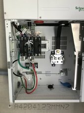
This is the main panel, so since it is NOT connected to the grid, should I take the screw out because of what you said about the Schneider having the N-G bond via a relay?Yes, Would recommend putting Neutral on the intended lug. Keeps things looking like a conventional system. The Green screw is the N-G bond. You will need to decide if you want that in the breaker panel or in the Inverter. I believe the Schneider has a dynamic N-G bond via a relay that closes when power is lost on AC1, which is always true in your off-grid situation.
Revisiting an earlier comment regarding L1 & L2. 400bird is correct in that it doesn't matter if the legs get reversed somewhere in the system but down the road its much easier to trace back problems if black and red are consistently used as L1 & l2 respectively.
Green screw in panel (check it's screwed down and not halfway in for shipping)So do I need to do something or did I do it correctly?
I'm out of State so can't do any testing till this weekend. However, go ahead and do what hwy17 outlined above. Everything will work fine.This is the main panel, so since it is NOT connected to the grid, should I take the screw out because of what you said about the Schneider having the N-G bond via a relay?
The Conext XW+ does not connect the neutral to ground. The AC input neutral isalready bonded to ground by the incoming utility grid system. Do not connect theneutral to ground in any additional location.The Conext XW+ does not switch or disconnect the AC neutral in any mode ofoperation, so even in invert (back-up) mode, the inverter load sub-panel neutralis bonded to ground by the utility grid system. It must not be grounded again inthe inverter load sub-panel.
Yes, all the other grounds are connected from the main panel. Main panel ground goes to the ground in the transfer switch. All the ground wires in the transfer switch go to that grounding bar, but no green screw there.Green screw in panel (check it's screwed down and not halfway in for shipping)
Transfer switch unbonded
Schneider unbonded
Generator unbonded
That's how I would do it. I think that's how you have it.
Ground rod goes to ground bar in main panel, all other devices get their ground from there.
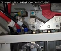
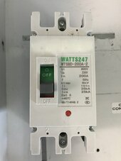
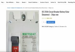
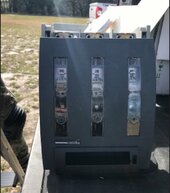
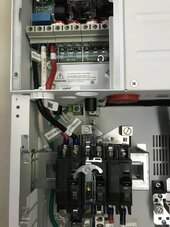
Not ready to turn on anyway, so will wait. Still have to hook batteries up and still trying to figure out this cut-off switch thing. I want a cut-off switch mounted right at the rack for the 6 EG4 V1 batteries in parallel which would then go to the busbars and then go to the inverter. That way, If I need to disconnect and move batteries out of the way, I can that without much trouble. I came into possession of a ton of Schneider things, one of which is this FUPACT. It has 3 250A breakers in it. I can't find much information on it, but if you pull the front, it seems as though it disconnects. I also have this 200A supposed DC rated breaker that I was going to use, but not sure which way to go.I'm out of State so can't do any testing till this weekend. However, go ahead and do what hwy17 outlined above. Everything will work fine.
What I do know is the Inverter has 5 relays on the PCB just above the AC1, Load & AC2 connection terminals. I was under the impression the 4 large relays are the transfer switches for AC1 & AC2 and the single, smaller relay was for the dynamic Neutral-Ground bond but I COULD BE WRONG. Will verify in a couple of days. Darn the bad memory.
I really appreciate you helping, I am such a novice. I saw David Poz say not to connect any neutral to the middle or generator connections, but he did connect at theIt'll be under "AC System Bonding" in the manual,
This is the quote from my XW+ manual:
Will go check it out. Thanks for taking the time to help.It'll be under "AC System Bonding" in the manual,
This is the quote from my XW+ manual:
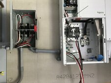
I am not leaving a dedicated generator outside for this to stay hooked to. Also, we were solely generator powered for a year, so we had a transfer switch wired because we wanted to eventually use a Growatt 12kw (which needed more things installed than the Schneider). Then, we switched gears and purchased a Schneider. Transfer switch is there already, so, if we needed to stay on Generator only (during hurricanes) we could just switch it over and disconnect the Schneider altogether (also lots of lightning and although I have surge protection, it can only take one lightning strike before it is toast) so during storms like that, I would rather lose a generator than the whole Schneider system.Happy to help. I'm just getting caught up with the thread. The part I'm confused about, and maybe you've got sorted out already, is the use of a PDP an a transfer switch. If the generator goes into the transfer switch that doesn't provide generator input to the XW.
Also I'm not sure about the purpose and location of the RV port but I don't think you're getting to that part of the install yet.
No problem I'll answer basic questions all day, if I am around.In my photo, I have the green wire from the transfer switch coming in and attached to the ground busbar. I see the grounding lug to the right with nothing attached to that. Since all I have connected is the LOAD OUT, what do I need to do to make sure I am only bonded once like you said? Do I need to anything with the white or green wires? I know this is so basic and not having a proper understanding concerns me to no end!
White neutral connects to N on Load out and then it goes on down to the Neutral bar right above the ground bar. Black (line 1) and Red (line 2) are hooked to the breaker (comes that way from Schneider. ) So black from the transfer switch goes to the bottom of the breaker and red from the transfer switch goes to the other side of the bottom of the breaker. Green from transfer switch which is bonded in the panel goes to the ground busbar.I can't see from the picture how those PDP jumpers work, but I trust that somehow those red and black do connect up through the one most left hand 60A breaker. It's ok if red and black get turned into black and red.
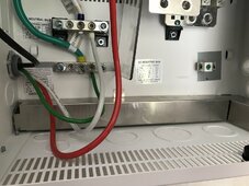
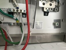
Great and somehow the XW chassis is grounded to the PDP ground right? I mean the two chassis are bolted together I just don't quite understand the ground lug at the top back of the PDP.White neutral connects to N on Load out and then it goes on down to the Neutral bar right above the ground bar. Black (line 1) and Red (line 2) are hooked to the breaker (comes that way from Schneider. So black from the transfer switch goes to the bottom of the breaker and red from the transfer switch goes to the other side of the bottom of the breaker. Green from transfer switch which is bonded in the panel goes to the ground busbar.
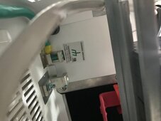
Me neither. I wonder if the Inverter is bonded to the mini pdp there.Great and somehow the XW chassis is grounded to the PDP ground right? I mean the two chassis are bolted together I just don't quite understand the ground lug at the top back of the PDP.

 diysolarforum.com

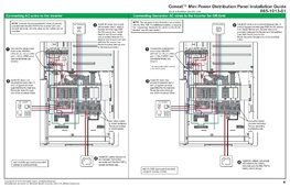
Oh there you go then. I just went and looked at my XW+ and realized I have the top lug too, it's actually a lug that is attached to the XW.Ok. I went to Ben's solar channel because he is the only one who has a video on the MINI pdp setup.
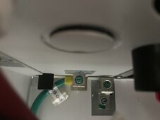
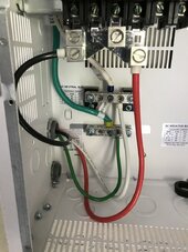
I took a few closer pictures for you to see, @hwy17, so the ground is on the busbar from the factory and it goes to the grounding lug labeled Chassis up in the top of the mini pdp. Ben says all neutrals go to the white busbar and the grounds go to the ground busbar.
THE THIRD PHOTO IS A SCREEN SHOT FROM BEN'S VIDEO SHOWING HE CONNECTED THE GROUND WIRE FROM THE BUSBAR AT THE BOTTOM OF THE MINI PDP (PRE-INSTALLED AT FACTORY) TO THE CHASSIS GROUND LUG (which matches my 2nd photo)