diy solar

diy solar

Schneider XW Pro commission

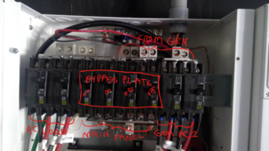
Good news you got the generator to charge.
You could probably up the charge rate to around 5kw on that generator. 75% of the max output is what I was always told to shoot for on a generator. But this also depends on your loads while charging, so it is site specific.
It looks like you have a large amount of solar coming in? Or will have? Depending on the weather where you live, you might not have to depend on the generator to fully charge the batteries and wait for the solar to do the rest.
 
After ten plus days with no sun to speak of, we are getting a week of it. Batteries are getting full already and I got the error message below. Any cause for alarm? What should I do about this?
 

Attachments

  • Schneider Electric - HMI Application4.pdf
    147.3 KB · Views: 8
Both inverters are showing this message. Dashboard shows batteries at 56.1V.
 

Attachments

  • Schneider Electric - HMI Application5.pdf
    168.8 KB · Views: 4
For Low battery cut out there is a way to change how close to cut out you will get the warning. I just looked at insight local and did not see a way to change the high battery cut out warning. You might have to change the high battery cut out to 58.3 so you don't keep getting those warnings.
 
The warning sets 3 volts below the cut out setting. I wish there was a way to adjust that 3 volts offset.

As far as I know, your options are:
Ignore the warning
Raise the HBCO setting, but this could allow the XW to try and charge above the cell's actual limits.

I went with option one, sorry I forget to tell people about the warning you'll get when fully charging the battery. This offset warning is documented in the manuals, but ugh, it's dumb.
My bad I thought the warning was 2 volts below hbco.
3 volts on a lithium battery is a big difference.
I guess I got lucky, my fortress battery is 55.2 volts for absorb charging and 58.5 hbco.
 
A few items:

I think that this is too many devices for the single XANBUS on an Insight Home. You're going to need Insight Facility for this because it's got 2 XANBUS networks. I'd probably put the MPPTs and Disconnect RSs on one, the 2 XW Pros, AGS, and BattMon on the other.
A characteristic of XANBUS saturation is communication errors between the XW's, slow refresh in Insight, and a bunch of other random behavior.

Did you go through the Standby calibration procedure to balance the Primary and Secondary voltage?

DC High Voltage alarms with LiPO4 on XW Pros can be a secondary symptom of BMSs cutout causing the DC bus voltage to spike.

Generator setpoints are tricky, looks like you already have that sorted.
 
Here is the complete schematic.
I started with the InsightHome and ended with the last inverter being terminated. If you look at the picture of my system, I start from the left and
ended with the last inverter on the right.
If anyone has any ideas on how to setup that AC buss with the generator feeding the inverter and setup to bypass such and feed the main panel, feel free to post. I'm working on it on this end.
Your biggest issue here is that the PDP breakers are designed to have Inputs on top and outputs on the bottom. Your main panel is not a current source, it is a load or current destination. In a system with a main "Grid Panel" and a "Backup Loads" panel, the grid panel is a source and the backup panel is a destination. You have only one panel.

To fix this you need to move the wires for the "Main Panel" from the top fingers on the four left most breakers to the bottom fingers on the four middle breakers. The rest of the design looks OK. Nothing will be connected to the Grid input because there is no grid connection.

When you turn the breakers associated with the inverter outs on, power will flow from the inverters, through the top of the Inverter out breakers, to those bottom fingers and then to your main panel.

When running the generator, the power will go from the gen to the top of the gen breakers. Then it will come out of there and run to the AC 2 or Gen inputs on both inverters. The inverters should go into pass through or possibly charging mode. In any case the power will come back to the inverter output breakers and flow down into the bottom fingers and back to the main panel. Those four middle breakers allow you to turn off the inverter breakers and turn on the "Grid Bypass" breakers. The interlock plate prevents having both of these on at the same time. If you did that on a system where the grid really was attached to the grid input fingers, you would be connecting your inverter output to the grid connection. That would be very dangerous and illegal. It could kill a lineman trying to work on a power line. You don't have to worry about that, but this is why they have the interlock plate.

The mistake here is that this drawing was assuming that your main panel would supply power to the grid terminals on the inverters. You don't have a grid so there should be no wires coming in those top fingers. You do however need to feed the main panel from those bottom fingers.

It would be possible to use the grid input for the generator, but I think that would just add more confusion. Until you understand how all this works, you probably shouldn't make changes. The AC 2 input essentially allows you to use the pass through mode of the inverter to power your house. This allows things like "gen support" to work as intended. All the labels on the breaker panel will be correctly labeled.

If you really want to bypass the inverters, the correct way would be to use a 4 pole double throw switch. The problem is you need to reroute both the generator destination and the main panel source at the same time. Get a price on a 200 amp 4PDT switch. You'll probably decide you don't really need this.
 
Last edited:
So the good news is the inverters are staying on. The Master shows 27.5 amps and the Slave shows 27.9 amps. InsightHome shows
3.3kw coming from the generator.
Thoughts?
You probably don't want to go too much higher in amps than that with your generator. I use voltage setting for setting the charging limits on my batteries. My experience is that I don't need to push voltage too high to get a full charge on the batteries. I run the bulk and absorption voltage both at 54.5. One of things about batteries is that you can get mine up to where it says it has 100% SOC fairly quickly. Then it will continue to add more into the battery at a slower and slower rate. It finally quits when charge current hits 6 amps. It might be most efficient to just get things 99% charged and then turn off the generator to save fuel. The small amount of extra charge just may not be worth the extra generator run time.
 
Thanks wheisenburg for the feedback. This is a picture of the most current AC buss configuration which seems to be working without a hitch.
I do have one question. Is it typical that the master always puts out more power than the slave and is this ok? For instance, not much draw right now but the master is putting out .13 kw and the slave about .03. These are constantly fluxuating but even as the load goes up, the master is doing more than the slave.
 

Attachments

  • AC buss config 022724.png
    AC buss config 022724.png
    2.4 MB · Views: 7
This is a picture of the most current AC buss configuration which seems to be working without a hitch.
This makes sense now. If it works and you understand how to use it, fine. If you decide to keep it the way it is. They do sell little label makers that could make sure you relabel things to avoid any confusion.

It would be a little more standard if you ran the loads up to where you now have the generator coming in. Then moved your generator link up the the upper left grids feed bar. The grids breakers would not go anywhere. The "Bypass Breakers" would feed the generator down to the loads fingers. Then the slide switch could select either Loads (inverter) or Bypass, which would be the generator. The plate would give you the mutual exclusion lock out.

Is it typical that the master always puts out more power than the slave and is this ok? For instance, not much draw right now but the master is putting out .13 kw and the slave about .03. These are constantly fluxuating but even as the load goes up, the master is doing more than the slave.

Mine does the same thing. On low loads sometimes the slave actually has just a "--". When running higher loads It starts to balance more. Did you check that both inverters are putting out the same AC voltage. Just turn the output breakers off and measure the AC across both inverter breakers. I they say in the manual what the tolerance it. If they are not the same (and out of tolerance), there is a way to adjust the voltage, but it is password protected. The master has shorter DC and AC cables. That might be enough to explain the difference.
 
Schneider includes a dead front for the PDP (which obviously isn't installed on the picture in post #70) with labels and extra labels to allow labeling some different options.

Also, I'm pretty sure the top/bottom position of connections is set by Schneider, from the installation manual:
Screenshot_20240227-174636.png
 
Back
Top