waterflea
New Member
- Joined
- Oct 9, 2022
- Messages
- 42
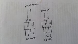
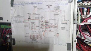
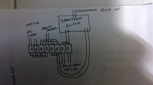
I need help. I have installed a 14.4kw solar system designed by Alt E and I am ready to commission but for a few problems. I have 2 XWPro Inverters, PDP, 3 Conext MPPT 100 600 charge controllers, 2 MPPT disconnect RS switches, Conext battery monitor, Conext AGS, InsightHome and 6 Pytes Ebox 48100R batteries. The first issue I had was getting the InsightHome to recognize the switches and battery monitor. I have checked and rechecked and have come to the conclusion the battery monitor is at fault and the switches? Who knows. I don't think it will matter much in the long run. The schematic below is what I have been using and was provided by Alt E. I'm having a hard time wrapping my head around their design for the AC buss. It seems too complicated for a total off grid system with only generator input. Am I wrong? I've tried their tech support and Schneiders and can't get a response. Please comment.