Do you mean the literal connections on the batteries or some way that I have things hooked together?That phrase is a classic bad connection symptom. I’m not convinced it’s the batteries.


You are using an out of date browser. It may not display this or other websites correctly.
You should upgrade or use an alternative browser.
You should upgrade or use an alternative browser.
Small system to power small freezer
- Thread starter Sonnyboy
- Start date
12VoltInstalls
life passes by too quickly to not live in freedom
Maybe. Or even inside the batteries is possible. I’m not saying that’s your problem but it’s worth evaluating before you start chasing your tail. It’s only a short leap from chasing one’s tail to chasing hubcaps and streaking in front of the town hall.Do you mean the literal connections on the batteries or some way that I have things hooked together?
Leeds
Solar Enthusiast
- Joined
- Jul 7, 2022
- Messages
- 179
You not using that output is why you have been able to drain your batteries so low, your CC has the ability to fix this but it's ut to you to use the functionality.So, your diagram is connecting to the "load" inputs on the SCC. Is that what you intended? I have never used the load outputs on a SCC.
Actually I just looked up your manual (I'm assuming it's a Tracer4215BN or very similar) and it appears that unlike the other Tracers, your model actually provides power from the load port, not a dry contact as all the older epevers (and most everyone else does).
For this reason I'd ament the drawing to be this:

Note that this still doesn't solve the root of your issues, it's just a nice way to wire it up so that you get some levels of protection against driving the inverter right down to where the battery BMS cuts out...
From what I presume to be your manual:
"Battery Over discharge [protection]: When battery voltage reach to the voltage set point of Low Voltage Disconnect Voltage, the controller will stop discharging the battery to protect the battery over discharged to break down. "
Seems like connecting the inverter to the load port is a bad idea though. I'm not sure if powering the Inkbird from the load port and then also having the Inkbird connected to the inverter to power it on is a mistake. To be honest, I've never used the load ports. I programmed the MT50 remote monitor to cut off 10.8 as per the battery specs so I guess it did what it was supposed to do. I'm worried I have something hooked up wrong for it to have drained so badly in one day.You not using that output is why you have been able to drain your batteries so low, your CC has the ability to fix this but it's ut to you to use the functionality.
Actually I just looked up your manual (I'm assuming it's a Tracer4215BN or very similar) and it appears that unlike the other Tracers, your model actually provides power from the load port, not a dry contact as all the older epevers (and most everyone else does).
For this reason I'd ament the drawing to be this:
View attachment 124948
Note that this still doesn't solve the root of your issues, it's just a nice way to wire it up so that you get some levels of protection against driving the inverter right down to where the battery BMS cuts out...
From what I presume to be your manual:
"Battery Over discharge [protection]: When battery voltage reach to the voltage set point of Low Voltage Disconnect Voltage, the controller will stop discharging the battery to protect the battery over discharged to break down. "
What is a Load, or "Low Voltage Disconnect" output?
Some controllers also have a "LOAD", or LVD output, which can be used for smaller loads, such as small appliances and lights. The advantage is that the load terminals have a low voltage disconnect, so it will turn off whatever is connected to the load terminals and keep from running the battery down too far. The LOAD output is often used for small non-critical loads, such as lights. A few, such as the Schneider Electric C12, can also be used as a lighting controller, to turn lights on at dark, but the Morningstar SLC lighting controller is usually a better choice for that. Do not use the LOAD output to run any but very small inverters. Inverters can have very high surge currents and may blow the controller.Most systems do not need the LVD function - it can drive only smaller loads. Depending on the rating of the controller, this may be from 6 to 60 amps. You cannot run any but the smallest inverter from the LOAD output. On some controllers, such as the Morningstar SS series, the load output can be used to drive a heavy duty relay for load control, gen start etc. The LOAD or LVD output is most often used in RV & remote systems, such as camera, monitor, and cell phone sites where the load is small and the site is unattended.
Leeds
Solar Enthusiast
- Joined
- Jul 7, 2022
- Messages
- 179
The load I'm suggesting you run on the port is the current draw to run the inkbird. It can be fused at least than one amp because it's only enough power to run the pic processor, drive a tiny relay and power the 7-segment displays.
The inverter is simply told to turn itself on and off by the inkbird. The inkbird IS NOT powering the inverter.
But when the CDC cuts off the courtesy power the inkbird shuts down and once off it cannot hold the inverter on anymore so that shuts down too.
The inverter is simply told to turn itself on and off by the inkbird. The inkbird IS NOT powering the inverter.
But when the CDC cuts off the courtesy power the inkbird shuts down and once off it cannot hold the inverter on anymore so that shuts down too.
oh gotchaThe load I'm suggesting you run on the port is the current draw to run the inkbird. It can be fused at least than one amp because it's only enough power to run the pic processor, drive a tiny relay and power the 7-segment displays.
The inverter is simply told to turn itself on and off by the inkbird. The inkbird IS NOT powering the inverter.
But when the CDC cuts off the courtesy power the inkbird shuts down and once off it cannot hold the inverter on anymore so that shuts down too.
Leeds
Solar Enthusiast
- Joined
- Jul 7, 2022
- Messages
- 179
Check your settings in your manual. Your CC is fancier than the older tracers and you can tell it to drive that port under different conditions.For some reason, my load port is not putting out anything. I have checked the mt50 parameters and it says the load is on. Anyone know why that might be?
RussNM
Solar Enthusiast
Have you checked to see if the LOAD button (the red on the right) on the epever has been inadvertently pushed? Unless its in a darker place it doesnt show up well. Also the buttons on the mt50 and the 4215 will sitck if pushed in too hard. Just a guess ....
Hi again,Check your settings in your manual. Your CC is fancier than the older tracers and you can tell it to drive that port under different conditions.
I recently got this I got about my CC from Epever:
“The difference between controller support with not support lithium battery is self activation and low temperature protection function.TracerBN doesn't have that function,so if battery trigger BMS protect,battery can't self activation.You must repower the controller to charge battery again,and that will have bad effect of battery.
You can set all the parameters in "User",but if battery trigger BMS protect that problem will happened.”
Given this info, do you know of an external Bms that I could wire into all of this?
EDIT: I just learned my batteries have internal smart Bms built in so all above is probably moot. Would’ve deleted post but couldn’t figure out how
Last edited:
Thanks to the many who have responded to this thread. I have taken a lot of your advice and put it into action. I have added two more 200w panels. So now my array is:
2 100w 22v 5.7a panels in series
2 100w 22v 5.7a panels in series
Then connected in parallel
And
2 200w 24v 10a panels in series
And then connected in parallel to the other panels. So one positive and one negative coming off the roof into the shed.
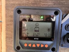
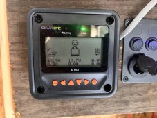
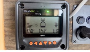
I am getting the following (images attached) readings and I am looking for feedback. Sometimes the MT50 reports 43v but nothing feeding the battery and sometimes it does charge the battery up to about 14.7. Is there a reason why the battery is at 12.6v and the panels are not charging it to capacity? I have attached the parameters that I have set. Also sometimes the MT50 reads the full 43 or so volts but 0 amps. Is that normal? Overcast day.
2 100w 22v 5.7a panels in series
2 100w 22v 5.7a panels in series
Then connected in parallel
And
2 200w 24v 10a panels in series
And then connected in parallel to the other panels. So one positive and one negative coming off the roof into the shed.
I am getting the following (images attached) readings and I am looking for feedback. Sometimes the MT50 reports 43v but nothing feeding the battery and sometimes it does charge the battery up to about 14.7. Is there a reason why the battery is at 12.6v and the panels are not charging it to capacity? I have attached the parameters that I have set. Also sometimes the MT50 reads the full 43 or so volts but 0 amps. Is that normal? Overcast day.
Attachments
Leeds
Solar Enthusiast
- Joined
- Jul 7, 2022
- Messages
- 179
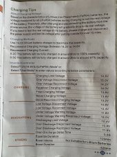
Your response from the manufacturer (post 70) suggests that you have a CC that doesn't support lifepo4 natively and they suggest you manually set all of the parameters under the "user" configuration menus.
So what battery type do you have it set for and what settings did you select under that battery type?
Showing the battery at 14.1V with an icon saying it's almost empty leads me to believe your configuration doesn't match your battery size or chemistry.
That said, I use the tracer AN series which deals with LiFePO4 natively so I've never dealt with that stuff. The AN's I have used have all had several LiFePO4 drop down options and I choose the 4s or 8s depending on which system I'm on, one of my 12V systems or my 24V system.
Perhaps someone else can comment more specifically about your BN controller if your user settings review doesn't crack the case right off the bat.
It is set as “user” with all of the settings in the photo attached.Your response from the manufacturer (post 70) suggests that you have a CC that doesn't support lifepo4 natively and they suggest you manually set all of the parameters under the "user" configuration menus.
So what battery type do you have it set for and what settings did you select under that battery type?
Showing the battery at 14.1V with an icon saying it's almost empty leads me to believe your configuration doesn't match your battery size or chemistry.
That said, I use the tracer AN series which deals with LiFePO4 natively so I've never dealt with that stuff. The AN's I have used have all had several LiFePO4 drop down options and I choose the 4s or 8s depending on which system I'm on, one of my 12V systems or my 24V system.
Perhaps someone else can comment more specifically about your BN controller if your user settings review doesn't crack the case right off the bat.
12VoltInstalls
life passes by too quickly to not live in freedom
It is set as “user” with all of the settings in the photo attached.
I’m no lithium expert but should not 14.6 be the max allowed period? Not 15V overvoltage disconnect?what settings did you select under that battery type?
Showing the battery at 14.1V with an icon saying it's almost empty leads me to believe your configuration doesn't match your battery size or chemistry
Similar threads
- Replies
- 18
- Views
- 618
- Replies
- 6
- Views
- 240
- Replies
- 10
- Views
- 540