That seems the only logical possibility.

Live long & prosper


That seems the only logical possibility.
What if I wired them to a manual cut off switch and activated them manually when the days were overcast?
Out of curiosity, which SCC do you have?I have 3,000W of panels on a 500W controller.
I have the Epever 40amp oneOut of curiosity, which SCC do you have?
I have Midnight controllers, and I know they will automatically clip off the peaks once the set limit is reached. For 48V, my set limit is 65A. I see my controller doing that around noon or so. It's not to much clipped off because of the panel orientation.So if I add say 600 or 1200 additional watts of panels to my system on overcast days will that fry my controller? When you say you are overpaneled, are you over your limit for what your controller can handle but because of placement it works? I would like to not have to upgrade to 24v at this time.
yeah but if I wire them the way you suggest I am just over wattage not over the controller 40ampsI have Midnight controllers, and I know they will automatically clip off the peaks once the set limit is reached. For 48V, my set limit is 65A. I see my controller doing that around noon or so. It's not to much clipped off because of the panel orientation.
Whether or not the budget model of the budget brand does exactly the same, I can't say for sure. What it's "supposed to do" and what it "actually can do" could be two different things. I"m assuming you don't want to find out by trying to run 80A through it.
I was actually asking @efficientPVI have the Epever 40amp one
I have a makeskyblue.Out of curiosity, which SCC do you have?
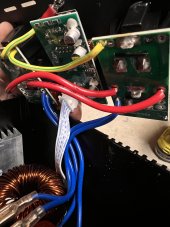
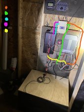
I don’t have two simple wires going to my rocker switch. I have it all on small boards with a white multithread cable going to it. Do you have any idea which is which?
So I soldered it as you said and it ndeed this did preserve a lot of battery. Now, a strange thing happens. Been working as you described for a few days, now the inkbird switched on( batteries at 14v) and immediately, the inverter begins beeping and battery voltage drops to 10.4. If I shut off the inkbird it jumps back up.I don’t have two simple wires going to my rocker switch. I have it all on small boards with a white multithread cable going to it. Do you have any idea which is which?
That's the sort of behavior I'd expect from a bad battery.So I soldered it as you said and it ndeed this did preserve a lot of battery. Now, a strange thing happens. Been working as you described for a few days, now the inkbird switched on( batteries at 14v) and immediately, the inverter begins beeping and battery voltage drops to 10.4. If I shut off the inkbird it jumps back up.
If I unplug the fridge, and keep the inkbird connected, yes, the inverter doesn't beep the warning. The batteries jump between 10.4-15v at random. The are brand new Weize lithium 100ah connected in parallel. So to be clear, the system says the batteries are at 14v, I switch on the Inkbird and the inverter beeps (low voltage error) and the batteries drop to 10v.That's the sort of behavior I'd expect from a bad battery.
If you unplug the fridge the inverter can probably power on for a while without tripping out like it does under load, right?


That phrase is a classic bad connection symptom. I’m not convinced it’s the batteries.The batteries jump between 10.4-15v at random.