BipedalPrimate
New Member
- Joined
- Mar 25, 2022
- Messages
- 61
Happy New Year to all you good people.
Planning/designing a Grid Tied ESS with Victron & DIY LiFePO4 to maximise self consumption.
This is the current state:

(Don't be too critical - the Heat Pump Hot Water was installed whilst I was in Europe & the installer simply replaced a 5kw Tank Hot Water system without thinking that it was on a Controlled Load Circuit. It was free upgrade - in Victoria, Australia. Works quite well but only between 11pm & 7am.)
This is the desired end state:

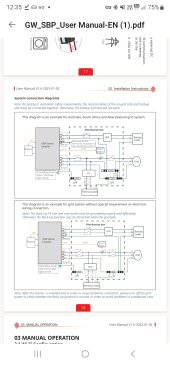
Victron (via their Wiring Unlimited guide) & others recommend that a Bypass Switch be installed to isolate the Multiplus II as follows:

Very useful advice BUT:
This is what I have come up with:

So, does a Bypass Switch exist that can handle this number of circuits/conductors?
Others on this site have suggested the VictorsHome Changeover Switch LW28-63 3 Positions 16 Terminals.
They provide a diagram of how it switches as follows:

When I try to map the required switching functions to this type of switch, it seems I need 32 terminals - not 16.

My questions to the wisdom of this crowd are:-
")
Planning/designing a Grid Tied ESS with Victron & DIY LiFePO4 to maximise self consumption.
This is the current state:
(Don't be too critical - the Heat Pump Hot Water was installed whilst I was in Europe & the installer simply replaced a 5kw Tank Hot Water system without thinking that it was on a Controlled Load Circuit. It was free upgrade - in Victoria, Australia. Works quite well but only between 11pm & 7am.)
This is the desired end state:
Victron (via their Wiring Unlimited guide) & others recommend that a Bypass Switch be installed to isolate the Multiplus II as follows:
6.6 AC bypass switch
It is recommended to add a manual bypass switch to an inverter/charger system. This is especially useful in mission critical systems. This switch allows you to bypass the inverter/charger and will connect the AC input (grid or generator) directly to the loads.
A switch like this will prove invaluable in case the inverter/charger needs a configuration change or should anything go wrong with the inverter/charger and it needs to be removed for service.
The bypass switch will need to break the AC in and AC out path to and from the inverter/charger and it then needs to make the bypass circuit. The switch needs to be rated to the full AC load of the system.
Very useful advice BUT:
- Notice in the To Be diagram above that the Fronius AC Inverter is connected to the AC1 Out of the Multiplus II
Maximum allowable feed in here is 5kw.
If Bypass Switch is used as per diagram, risk of feeding in 6kw exists - not a discussion I wish to have with the electricity distributor here.
To manage that limit, there is a Fronius Smart Meter installed between the Grid and the Fronius AC Inverter in the As Is diagram above - it is not shown.
That Fronius Smart Meter must be removed when connecting the Fronius PV Inverter to the AC1 Out of the Multiplus II.
The Cerbo GX manages the output limiting of the Fronius PV Inverter via MODBUS TCP. - Further to 1, if we leave the Fronius PV Inverter outside the scope of the Bypass Switch and remaining connected to Multiplus II AC1 Out, there will still be 230v with variable current (depending on battery SOC & idle current) going to the Multiplus II.
The Fronius AC Isolation Switch could be used to disconnect but someone needs to remember to do that before touching anything. - There are two AC Out connections on the Multiplus II.
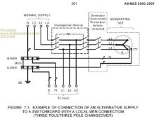
Both will need to be switched by the Bypass Switch. - Under normal situations with the Grid active, there is an Earth-Neutral connection in the switchboard.
The Multiplus II maintains that connection to that single Earth-Neutral connection until the Grid fails.
On Grid failure, the Multiplus II then disconnects the AC In (A & N) and creates its own Earth-Neutral connection internally.
(In Australia, the tendency is to use the word Active rather than Live as in Active Conductor instead of Live Conductor)
When Bypass Switch is used, both A(ctive) & N(eutral) will need to be switched to ensure there is an active Earth-Neutral connection in the circuit. That is, cannot leave the Neutral conductor connected to the Multiplus II.
This is what I have come up with:
So, does a Bypass Switch exist that can handle this number of circuits/conductors?
Others on this site have suggested the VictorsHome Changeover Switch LW28-63 3 Positions 16 Terminals.
They provide a diagram of how it switches as follows:
When I try to map the required switching functions to this type of switch, it seems I need 32 terminals - not 16.
My questions to the wisdom of this crowd are:-
- Have I made any incorrect assumptions?
- Am I overthinking what needs to happen?
- Are there any alternatives to VictorsHome Changeover Switch that will do the job?
- Are there other solutions (other circuit switching devices) that will work?
- Other comments welcome.