You are using an out of date browser. It may not display this or other websites correctly.
You should upgrade or use an alternative browser.
You should upgrade or use an alternative browser.
Megarevo RxLNA Discussion
- Thread starter jsmetalcraft
- Start date
NCSolarGarage
13.2kW Off-Grid
- Joined
- Sep 23, 2021
- Messages
- 209
So I asked MR to update my data logger.
And suddenly I see lots more details:
Glad to hear they were able to update easily and it worked!
Okay, I got this thing communicating with a usb rs485 adapter. The issue was the pinouts I listed in a previous post. All were showing wrong. The bottom side of my inverter connector pin numbers matche the picture shown by flygeek holding the wifi adapter. The pinout listed on both the solarman and solar-assistant page are incorrect for mine. I figured this out by checking the voltages and here is the working pinout on mine.
5v = 1
2 = B
3 = A
4 = GND
Now, it could be that mine is a 1 off and the other end of the connector on the main board is incorrect or something neat like that but this talking fine with a cheap usb to rs485 adapter.
I was also able to use minimalmodbus python program to poll the registers listed in the modbus spreadsheet I listed before. This is a sample of pulling the register with a python script to pull battery SoC % through the inverter:
#! /usr/bin/python3
import minimalmodbus
import serial
import time
instrument = minimalmodbus.Instrument('/dev/ttyUSB0', 1)
instrument.serial.baudrate = 9600
instrument.serial.bytesize = 8
instrument.serial.parity = serial.PARITY_NONE
instrument.serial.stopbits = 1
instrument.serial.timeout = 5
data = instrument.read_registers(12613, 1) # Registernumber, number of decimals
print(data)
fromport
Solar Addict
Are you going to poll all data yourself or going to use some existing setup?I was also able to use minimalmodbus python program to poll the registers listed in the modbus spreadsheet I listed before. This is a sample of pulling the register with a python script to pull battery SoC % through the inverter:
If somebody gets a minute and is able to use a digital multimeter, can you check the pinout I just posted was how mine is setup? The 5v pin to the inverter chassis ground screw should measure around 4.5v dc, ground screw to gnd pin should be 0 volts and the remaining 2 to ground screw are around 2.5v.
It would be nice to know if mine is like this or if all are the same.
It would be nice to know if mine is like this or if all are the same.
NCSolarGarage
13.2kW Off-Grid
- Joined
- Sep 23, 2021
- Messages
- 209
Well my pinout matches yours however I got 2.5 volts on pin 1 and 1.25 on the others. This was going to the ground screw right behind the com port
2.5 is a weird reading. I wouldn’t think the SOLARMAN dongle would work with less than 3.3v. Maybe measure between the ground pin and 5v pin?Well my pinout matches yours however I got 2.5 volts on pin 1 and 1.25 on the others. This was going to the ground screw right behind the com port
fromport
Solar Addict
I upgraded my firmware to the latest version.

I had like 3 errors after the first file upgrade (and automatic reboot)
After the 2nd file (ultra fast reboot) i had like 6 errors and no power.
Shut down PV, Grid & battery : waited 10 seconds after everything went dark and turned on batteries.
turned on PV & grid and everything came back to live.
No more errors.
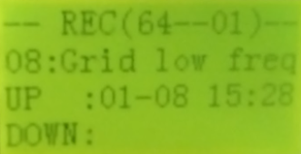
I saw an "RECORD" in the menu and I assume it is some kind of logging:

Will keep an eye on this release to see how it works.
**UPDATE**
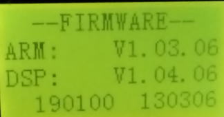
Screenshot with version info from the solarman screen:


I had like 3 errors after the first file upgrade (and automatic reboot)
After the 2nd file (ultra fast reboot) i had like 6 errors and no power.
Shut down PV, Grid & battery : waited 10 seconds after everything went dark and turned on batteries.
turned on PV & grid and everything came back to live.
No more errors.
I saw an "RECORD" in the menu and I assume it is some kind of logging:

Will keep an eye on this release to see how it works.
**UPDATE**
Screenshot with version info from the solarman screen:

Last edited:
NCSolarGarage
13.2kW Off-Grid
- Joined
- Sep 23, 2021
- Messages
- 209
This doesn't have generator function, correct?
fromport
Solar Addict
Can someone help me interpret the values I see from solarman ?
I am grid tied and in "self consume" mode
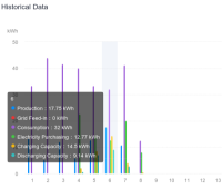
Data from day before yesterday:

Blue: PV production: 17.75 kWh [clear: DC energy from my 2 strings of panels connedted]
Red: Grid feed-in: 0 kWh [clear: AC rated, my batteries never got to 100% charged so no export]
Purple: Consumption: 32 kWh [clear: what my AC loads used behind the inverter]
Green: Electricity purchased [clear: AC power that was fed from grid through inverter to my loads]
12.77 + 17.75 = 30.53 kWh, comes close to the "Consumption" of 32kWh.
This is where I don't get it:
Yellow: Charging capacity: 14.5 kWh So the PV took over load first. If it had more energy than the load required, it would charge my batteries.
It put 14.5 kWh in the batteries? That is 14.5/17.75 = 82% of what PV generated?
That doesn't sound right, I am pretty sure I used a lot more to power the loads during the day (electric heating since it is winter)
blue/green: discharging capacity 9.14 kWh
If that is the amount of energy that was withdrawn of the battery after charging it with 14.5 kWh, that would mean we only have 63% efficiency storing energy in the battery.
Again: that doesn't seem right.
Any ideas/feedback ?
I am grid tied and in "self consume" mode
Data from day before yesterday:

Blue: PV production: 17.75 kWh [clear: DC energy from my 2 strings of panels connedted]
Red: Grid feed-in: 0 kWh [clear: AC rated, my batteries never got to 100% charged so no export]
Purple: Consumption: 32 kWh [clear: what my AC loads used behind the inverter]
Green: Electricity purchased [clear: AC power that was fed from grid through inverter to my loads]
12.77 + 17.75 = 30.53 kWh, comes close to the "Consumption" of 32kWh.
This is where I don't get it:
Yellow: Charging capacity: 14.5 kWh So the PV took over load first. If it had more energy than the load required, it would charge my batteries.
It put 14.5 kWh in the batteries? That is 14.5/17.75 = 82% of what PV generated?
That doesn't sound right, I am pretty sure I used a lot more to power the loads during the day (electric heating since it is winter)
blue/green: discharging capacity 9.14 kWh
If that is the amount of energy that was withdrawn of the battery after charging it with 14.5 kWh, that would mean we only have 63% efficiency storing energy in the battery.
Again: that doesn't seem right.
Any ideas/feedback ?
fromport
Solar Addict
I didn't look for it in the menu since I don't use it, but according to the technician who provided me the software, he said it should have it.This doesn't have generator function, correct?
Do you have a generator hooked up that automatically comes on when not enough PV/batteries are available?
JohnZEBSolar
New Member
- Joined
- Dec 12, 2022
- Messages
- 22
Does anyone have an issue after firmware upgrade.
It seams like every time I do an upgrade to these, pv production stops almost completely, middle of day, full sun.
wondering if anyone else has these problems, or possible solutions?
Thanks
It seams like every time I do an upgrade to these, pv production stops almost completely, middle of day, full sun.
wondering if anyone else has these problems, or possible solutions?
Thanks
NCSolarGarage
13.2kW Off-Grid
- Joined
- Sep 23, 2021
- Messages
- 209
Whenever I update, I turn off the PV disconnect switch so it doesn't keep turning on/off during the update reboots. THEN after update when I turn PV disconnect back on, PV resumes
JohnZEBSolar
New Member
- Joined
- Dec 12, 2022
- Messages
- 22
I shut down pv, and battery, then do upgrade with only grid connect. My PV drops out then bounces very low over the next few hours/daysWhenever I update, I turn off the PV disconnect switch so it doesn't keep turning on/off during the update reboots. THEN after update when I turn PV disconnect back on, PV resumes
JohnZEBSolar
New Member
- Joined
- Dec 12, 2022
- Messages
- 22
and, of course, turn pv and battery back on.I shut down pv, and battery, then do upgrade with only grid connect. My PV drops out then bounces very low over the next few hours/days
NCSolarGarage
13.2kW Off-Grid
- Joined
- Sep 23, 2021
- Messages
- 209
Have you tried a reboot after update?
JohnZEBSolar
New Member
- Joined
- Dec 12, 2022
- Messages
- 22
JohnZEBSolar
New Member
- Joined
- Dec 12, 2022
- Messages
- 22
yesHave you tried a reboot after update?
Similar threads
- Replies
- 211
- Views
- 14K
- Replies
- 30
- Views
- 3K
- Replies
- 5
- Views
- 429


![Screenshot_20230110_121619_SOLARMAN_Smart[1].jpg Screenshot_20230110_121619_SOLARMAN_Smart[1].jpg](https://diysolarforum.com/data/attachments/128/128878-0060bcedac436fde96e319ea5e525a36.jpg)