diy solar

diy solar

Schneider XW Pro Multi Inverter Setup Limits

Darcy Costa Rica

New Member
Joined
Jun 3, 2022
Messages
39
Hi, I'm trying to install 3 Schneider XW Pro inverters. It seems there is a warning about using 3 of these that I do not understand. Are there any Schneider Experts out there who can explain where the problem is when using 3 inverters? This is the quote from the installation manual:

EQUIPMENT DAMAGE
  • The Automatic Transfer Relays are rated at 60 A.
  • Loads connected at AC OUT must not exceed the inverter's overload ratings or the 60 A limit, whichever is lower. Unless an external contactor or external transfer switch (such as the Schneider Electric BCS) is used, the 60 A limit also applies to the total combined loads connected to the AC OUT bus of multiple inverters connected in parallel.
The electricity is so bad here in Costa Rica, I am planning on using the inverters to power my house all the time, and only using the grid for charging the batteries if the sun does not shine enough during the rainy season. So, I do not expect to be transferring from the grid to PV and back due to power outages.

I have installed a 200 Amp Eaton transfer switch that I will use when servicing the inverters. Otherwise, the property will always be powered by the Schneiders. With over 20 KW of power from the 3 inverters, I do not think I will ever exceed their power.

Many thanks. I will be posting quite a few questions as I am finally starting to install my system. Totally DIY.
 
When multiple inverters are connected in parallel they sync with regard to the AC Outputs but each inverter is still controlling its own internal transfer switch so there is no guarantee that all 3 will open or close at exactly the same time meaning All the power will momentarily flow through only one transfer relay if it is the first to close or last to open.
In your situation, if the grid is going to be disconnected and you will not be using the Automatic Transfer capabilities of the inverters its not going to be a problem. You will have to remember not to connect to grid anytime there is more than a total of 60A demand from the loads and battery charger maximum bulk amperage setting.
 
BTW, are you planning on using the Schneider PDP. Would be advisable with 3 inverters and 2 charge controllers so you have a common junction box with built in breakers to make all the connections.
 
I like to hear from folks that have two or more of these unites without the external switch and had issues with a normal residential house. Is this 60A per leg or 60A across the two ..so 30A each leg? I could see myself exceeding this in the winter with the Heater, dryer, oven and normal other stuff going. I forgot about this limitation! I wish they'd update these units to have 100A per leg like the new solarks.
 
Wonder if outback has this limitation and needs a external relay. I asked on the outback forum and they didn't seem to think it did.
 
Is this 60A per leg or 60A across the two ..so 30A each leg?
With Schneider its 60A per leg which is: 60A x 240V = 14,400W of total pass thru power. This is double the continuous output capacity of the inverter so I suppose they feel like it's more than adequate to operate a critical loads panel.
What would be really helpful is to increase the transfer relay to 100A or even 200A and add a few load control aux relays that could be used to shut off non essential loads when the grid is down. Surprised Schneider hasn't figured this out yet.
 
I agree, I can't believe they haven't put 100A per leg relays. Most residential house in the USA are 200A right..100A per leg? I suppose even the guys that sting up 4 mpp have this issue to. 14k watts isn't that much for a all electric house. I guess the way to do it without the external relay is to split the main panel into two and have one inverter power each side. That relay for the XW is $3k.
 
I agree, I can't believe they haven't put 100A per leg relays. Most residential house in the USA are 200A right..100A per leg? I suppose even the guys that sting up 4 mpp have this issue to. 14k watts isn't that much for an all electric house. I guess the way to do it without the external relay is to split the main panel into two and have one inverter power each side. That relay for the XW is $3k.
200a is 200 per leg. Would an automatic transfer switch work in place of a $3k relay?
 
Most residential house in the USA are 200A right..100A per leg?
That is not how it works. A US breaker panel that is rated at 100, 125, 200, 225, 400A Etc is a per bus bar rating. So split phase has 2 bus bars and 3 phase has 3 bus bars. In both cases each bus bar is rated at the same value as stated on the panel. So a 100A split phase panel has a 2 pole 100A main and a 3 phase panel has a 3 pole, 100A main. Translation: any or all of the bus bars would be able to carry up to 100A individually regardless of what is happening on the other bus bars. If one leg trips it does however, trip the other legs.

We are disregarding the 80% design rule for this example.
 
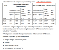
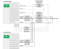
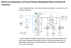
The way Schneider addresses the 60A limit is to use an external contactor.


The contactor is controlled by a relay:


I was going to put this in my system, but thus far, have not exceeded the 60A internal relay limit, so no need for the external contactor yet.

This might be a solution for your situation?
with_external_contactor copy.png
Schneider_external_relay_contactor copy.png
schneider_electrical_configuration.png
 
Last edited:
200a is 200 per leg. Would an automatic transfer switch work in place of a $3k relay?
I'm sure it could be done. The Schneider has an aux output specifically for operating an external transfer switch. I don't recall the specifics if its dry contact or 12V but it wouldn't be difficult to use with a 3rd party device as long as you could convert inverter output to what is needed by the ATS as far as the control signal voltage.
 
Per google.

200-amp service is the current standard for new homes and updated service panels. It can supply all standard electrical needs in a typical family home but may not support a large electric heating system. In large homes, 300-amp or larger service capacity may be needed, particularly if the home has electric heating.Nov 15, 2022

So, I assume they are saying 100A per leg is average in USA for split phase? This isn't correct?
 
Again, a 200A service would be 200A per leg. This standard applies more for all electric homes and larger custom homes. Here in CA where we have Nat Gas, 100A service is very common and more than adequate. Realistically, most homes don't need 200A but are forced to upgrade to higher capacity panels that have more breaker spaces and allow for larger solar installations.
 
Again, a 200A service would be 200A per leg. This standard applies more for all electric homes and larger custom homes. Here in CA where we have Nat Gas, 100A service is very common and more than adequate. Realistically, most homes don't need 200A but are forced to upgrade to higher capacity panels that have more breaker spaces and allow for larger solar installations.
Ah, ok. Thanks for explaining it.
 
The way Schneider addresses the 60A limit is to use an external contactor.


The contactor is controller by a relay:


I was going to put this in my system, but thus far, have not exceeded the 60A internal relay limit, so no need for the external contactor yet.

This might be a solution for your situation?
View attachment 142156
View attachment 142159
View attachment 142163
Curious if you house is all Electric? Is you're whole house wired into this inverter...AC,heater,oven,dryer and all the other junk like tv, microwave etc? I'm concerned about using multiple large appliances at once and it being a issue.
 
BTW, are you planning on using the Schneider PDP. Would be advisable with 3 inverters and 2 charge controllers so you have a common junction box with built in breakers to make all the connections.
Yes, I have the PDP. I agree, it is extremely valuable with this system configuration.
 
When multiple inverters are connected in parallel they sync with regard to the AC Outputs but each inverter is still controlling its own internal transfer switch so there is no guarantee that all 3 will open or close at exactly the same time meaning All the power will momentarily flow through only one transfer relay if it is the first to close or last to open.
In your situation, if the grid is going to be disconnected and you will not be using the Automatic Transfer capabilities of the inverters its not going to be a problem. You will have to remember not to connect to grid anytime there is more than a total of 60A demand from the loads and battery charger maximum bulk amperage setting.
Thanks for the reply, but I think I need a little clarification. The grid will be connected to the inverters through the PDP. This is so I can use the battery charger in the inverters to recharge the batteries in case the sun doesn't shine for a few days.

I do not want to have the inverters switch from Battery generated power (inverter power) to Grid power automatically. I am hoping I can set the inverters to avoid this. If I am going to do some maintenance, I will probably power down most of the property before using the manual switch between Battery power and Grid Power.
 
I do not want to have the inverters switch from Battery generated power (inverter power) to Grid power automatically. I am hoping I can set the inverters to avoid this. If I am going to do some maintenance, I will probably power down most of the property before using the manual switch between Battery power and Grid Power.
The only way to be 100% sure the inverter does not switch over to grid usage is to leave the AC input breakers off but this may not be ideal as it is then possible for the batteries to discharge down to the LBCO setting and the inverter shuts down completely. Better to leave the input breakers on and Disable Charging on the user menu. At least this way the inverter will automatically go into grid pass-through mode and battery draw is reduced to only stand-by current, 500mA or less. Much less chance of having the whole system shut off at LBCO. If you decide to use grid for battery charging then you manually Enable charging and manually "Force" a Bulk Charge cycle.

If the XW Pro AC charger is Enabled there are 4 conditions that will initiate a bulk charge. (As long as the Charge Block timers are not active)
1) Battery Volts = Recharge Volts Setting.
2) EDIT: Battery Volts = LBCO Setting +1.0V. LBCO +2.0V only throws a low voltage warning alarm.
3) Grid power is On and gets interrupted. A Bulk charge cycle is initiated when grid power returns.
4) A Bulk Charge cycle is forced via the user menu.

There are so many options, it can get confusing. It may be helpful to write down a bulleted wish list of your desired modes of operation and we can help come up with suggested initial settings.
 
Last edited:
Is you're whole house wired into this inverter
No, I only connected some loads to the solar: Well pump, pool pumps, heat pump compressor, water heater, some other smaller loads.
The rest of the house is on grid: oven range, clothes dryer, heat pump air handler - (due to the 15kw load of the heat strips).

When the grid is down, we switch the entire house to solar, and carefully manage which loads are active.

I have the Schneider configured for "grid support", so when there is no/limited Sun, the inverters supplement the load from grid.
The system runs the loads from the PV, the batteries are in standby, only used for a few seconds for the transition to grid support, or when there is a grid failure.
 
The internal relays are electro/mechanical. During a grid fail/disqualify, these relays open and switch to invert mode. Obviously the relays have maximum current limitations. Relays use magnetic energy to close and springs to open. A typical Schneider Tesys D DT60A 60A contactor has an advertised closing time 12-26ms and opening time of 4-19ms. Due to the large variation in opening time due to spring constants being different, multiple paralleled relays do not open at the exact same time. Each relay has a maximum continuous current rating and also a maximum current breaking rating. Due to the staggered opening times, it is technically possible, under a worse case scenario that a single relay would be burdened with breaking more current when opening than its rating. If this scenario happens, the relay contacts would not break open, would weld themselves shut, and then would backfeed inverter battery output power to the grid. There is no double failsafe, only a single relay. What you have to understand is relay contacts are arcing while opening under load, the arc starts as they open, then quench/extinguish as they open fully. This contact material is designed to "clean" itself due to this arcing and also withstand the arcing/quenching of the arc. If a contact is being subjected to breaking currents in excess, it simply will weld due to the temperatures at the contact surfaces, exceeding the design limits and melting instead of cleaning/opening like normal. Due to 60Hz having a 16.666ms period, a difference of this amount of time between all contactors opening would easily force a single relay to carry 3X the breaking current for an entire cycle, while opening, in a 3 inverter setup. This is why they state 3 or more require an external transfer switch.

Inside the XW the relays are soldered onto the board and not easily replaceable. Outback either ignores this reality or uses larger relays with a higher rating. I believe in the radian, they are mounted in such a way to allow easier changing than Schneider. I believe the Radian relays are soldered in also, but is a faster swap. Cant remember.

I can tell you that the XW units 3 or more is a huge bummer due to loss of features when using an external contactor, switch, or BCS unit. There is additional cost for this hardware that is far cheaper than having a welded relay backfeed a line and violate UL listing and potential hurt a lineman. Backfeeding the grid is impossible with such a small inverter, but under a worst case scenario, could energize a small section of power lines and kill a lineman let alone damage your equipment.

The Schneider BCS unit is essentially a whole house transfer switch. It does the heavy switching instead of the internal relays. You loose generator inputs and UPS style functionality. AC coupling is also more tricky,

Using 3 or more XW's is possible without such additional hardware, it will work, but not from a manufacture manual, reliability, technical position. If inspected and found, you would be in violation of the manufactures instructions, with is a NEC violation and would be shut down/red tagged by the POCO. Most POCO's know the UL1741 standards, which manufactures comply, and how they work. Some POCO's go as far as approved inverter list. Not all POCO's are super thorough, they simply look for UL1741 approvals when doing reviews.
 
Last edited:
The internal relays are electro/mechanical. During a grid fail/disqualify, these relays open and switch to invert mode. Obviously the relays have maximum current limitations. Relays use magnetic energy to close and springs to open. A typical Schneider Tesys D DT60A 60A contactor has an advertised closing time 12-26ms and opening time of 4-19ms. Due to the large variation in opening time due to spring constants being different, multiple paralleled relays do not open at the exact same time. Each relay has a maximum continuous current rating and also a maximum current breaking rating. Due to the staggered opening times, it is technically possible, under a worse case scenario that a single relay would be burdened with breaking more current when opening than its rating. If this scenario happens, the relay contacts would not break open, would weld themselves shut, and then would backfeed inverter battery output power to the grid. There is no double failsafe, only a single relay. What you have to understand is relay contacts are arcing while opening under load, the arc starts as they open, then quench/extinguish as they open fully. This contact material is designed to "clean" itself due to this arcing and also withstand the arcing/quenching of the arc. If a contact is being subjected to breaking currents in excess, it simply will weld due to the temperatures at the contact surfaces, exceeding the design limits and melting instead of cleaning/opening like normal. Due to 60Hz having a 16.666ms period, a difference of this amount of time between all contactors opening would easily force a single relay to carry 3X the breaking current for an entire cycle, while opening, in a 3 inverter setup. This is why they state 3 or more require an external transfer switch.

Inside the XW the relays are soldered onto the board and not easily replaceable. Outback either ignores this reality or uses larger relays with a higher rating. I believe in the radian, they are mounted in such a way to allow easier changing than Schneider. I believe the Radian relays are soldered in also, but is a faster swap. Cant remember.

I can tell you that the XW units 3 or more is a huge bummer due to loss of features when using an external contactor, switch, or BCS unit. There is additional cost for this hardware that is far cheaper than having a welded relay backfeed a line and violate UL listing and potential hurt a lineman. Backfeeding the grid is impossible with such a small inverter, but under a worst case scenario, could energize a small section of power lines and kill a lineman let alone damage your equipment.

The Schneider BCS unit is essentially a whole house transfer switch. It does the heavy switching instead of the internal relays. You loose generator inputs and UPS style functionality. AC coupling is also more tricky,

Using 3 or more XW's is possible without such additional hardware, it will work, but not from a manufacture manual, reliability, technical position. If inspected and found, you would be in violation of the manufactures instructions, with is a NEC violation and would be shut down/red tagged by the POCO. Most POCO's know the UL1741 standards, which manufactures comply, and how they work. Some POCO's go as far as approved inverter list. Not all POCO's are super thorough, they simply look for UL1741 approvals when doing reviews.
Thank you for the excellent explanation of the problem that having multiple inverters can cause. I have a couple of questions that I think you may be able to help me with.

First, if you have two inverters, and your potential load was more than 60 Amps, couldn't they have the same problem? Couldn't the relays still try to carry the current in an unbalanced way creating the same overload/welding failure?

Second, if I am only planning on using the Grid for emergency battery charging, is it possible to set up the XW Pro so it never attempts to power the backup loads panel through the Grid? If this is possible, there should never be relay switching from PV to Grid and back.

I am going to write up my scenario and, in a new thread, ask for assistance on the best way to configure the inverters.

Thanks again.
The manual on page 25 has the various setups and it does say two inverters without all the external stuff is supported. I'm not sure why over two brings all this into play.


Also, over at the outback forum I posted above users are saying they never seen this requirement for radians. Have you considered a outback? While I don't have experience with either one from what I've read and been told the radians are battle tough and reliable. I had a installer tell me that the xwpros are dam near unbreakable but that the radians are almost the same. Seems like people like the raidan software better to.

 
Last edited:
The manual on page 25 has the various setups and it does say two inverters without all the external stuff is supported. I'm not sure why over two brings all this into play.


Also, over at the outback forum I posted above users are saying they never seen this requirement for radians. Have you considered a outback? While I don't have experience with either one from what I've read and been told the radians are battle tough and reliable. I had a installer tell me that the xwpros are dam near unbreakable but that the radians are almost the same. Seems like people like the raidan software better to.

They are mounted on the wall. Too late for those kind of thoughts. :)
 
First, if you have two inverters, and your potential load was more than 60 Amps, couldn't they have the same problem? Couldn't the relays still try to carry the current in an unbalanced way creating the same overload/welding failure?

Second, if I am only planning on using the Grid for emergency battery charging, is it possible to set up the XW Pro so it never attempts to power the backup loads panel through the Grid? If this is possible, there should never be relay switching from PV to Grid and back.
1. Answer to first Q. Probably not. A relay's continuous current rating is X, its breaking current rating is typically 2-5X (depends on manufacture datasheet). So assuming you had 2 XW's, operating in AC passthrough of 120A load (60A each), had a grid down scenario, both XW relays open, inverter would output a max of 104A (52A Each) and loads would not drop, this is 100% acceptable per the Schneider manual. It is an allowed configuration per their multi unit specs/manual.

2. Answer to second Q. Yes, but not how you explained. The inverter is bidirectional to/from all energy sources. This is the hard part to understand. See the picture below of the functional power block (user manual pages 24-26). If at any time AC1 OR AC2 relays are closed, it CAN power the loads based upon the operational modes programed. To answer your question fully, the XW can operate in "Grid Support" mode (user manual pages 80-83) and if properly configured, can provide exactly what you want (only use AC to keep batteries up and to not power loads directly). Understand, it could only do this based upon parameter settings and there will be some AC grid current at all times no matter what, a few watts best case scenario.
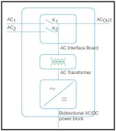
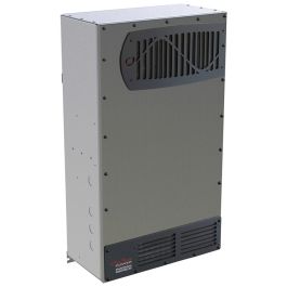
XW Pro.jpg

Understand, the XW allows unlimited configurations due to the many parameters. Most people/installers get them set incorrectly and the units behave incorrectly, and they get a bad name/reviews/bashing. The XW is really an engineers wet dream, not a DIY 1 button configuration. I am not partial to either XW or Radian. I believe the XW to be a better product due to the ecosystem of accessories and level of integration. Not to mention it is Schneider electric which is not going anywhere. The Con is you pay for it $$$. The Outback Radian solution is equally comparable. In my eyes, their ecosystem/software is not as polished, but offers higher total output KW, but less surge KW/to full KW ratios as the XW. Both are LF inverters, the top of the food chain from each, and both are winners. As an EE, with OCD, I find the minor differences between the two.

In regard to the 3 or more unit requiring external relays. Schneider has taken the upfront, visible analytical approach as said, if 3 or more XW's used, the probability of failure has risen due to the reduction of lifespan, which increases liability due to welding failure, reduces lifespan of the relay/inverter, increases warranty cost, and carries risk associated to UL listings/possible back feed, and therefore we suggest using an external contactor. Understand no company who makes relays for a living is going to say that it is ok to operate outside its datasheet specifications. The datasheet has specs for everything, including lifespan. The XW is an old design, from Xantrex, carried over to Schneider. The market really needs 200A internal bypass ratings like the Sol-Ark 15K, but minus the other firmware/HF inverter headaches, I digress.

What you/everyone is missing is that Radian has an identical limitation, but goes unnoticed. Per the Radian installation manual, when using 2 or more (up to 10), you cannot enable Grid Support or Grid Zero modes. These modes would close the internal transfer relay all the time, and it would be subjected to the same exact scenario as the XW that I have described previously. Radian does not come out and tell you "NO! Don't do it" like XW, they bury the comment in the installation manual, that is a tiny footnote, that references the user manual. XW clearly calls it out and says NO. The exact reason why Radian says no to these 2 modes of operation is exactly the reason XW says you cannot do 3 or more units in parallel without an external bypass contactor. It is Radian marketing of saying "look, we can do 10 in parallel!". Both inverters are subject to the same restriction, yet one manufacture is up front about it. Read page 41 Important footnote of the radian installation manual.

"Do not use the AC input modes Support or Grid Zero in a stacked system. See the Operator’s Manual."

FYI, I am not affiliated with NOR rep either brands. I simply provide custom solutions that work.
 
Last edited:

diy solar

diy solar
Back
Top