diy solar

diy solar

EG4 6000EX and power on one of the legs

priorityelec

New Member
Joined
Sep 11, 2020
Messages
37
The EG4 6000EX runs 240 volts on two legs. Does it max out at 3000 on each leg? If I have a sub panel and one leg goes to one side, the other leg to the other side...what happens if one side of the panel (through a few breakers) wants to draw for example 4000 watts?
 
The EG4 6000EX runs 240 volts on two legs. Does it max out at 3000 on each leg?

Yes.

If I have a sub panel and one leg goes to one side, the other leg to the other side...what happens if one side of the panel (through a few breakers) wants to draw for example 4000 watts?

Inverter overload. It's important you balance your panel/loads.
 
I believe the 6000ex is a low frequency inverter. It has a built in transformer. It wouldn’t suffer from the issue of one leg being overloaded. So 4K on one leg and 2k on the other would work fine with that inverter. This makes the idle consumption a bit higher though.
 
Last edited:
I believe the 6000ex is a low frequency inverter. It has a built in transformer. It wouldn’t suffer from the issue of one leg being overloaded. So 4K on one leg and 2k on the other would work fine with that inverter. This makes the idle consumption a bit higher though.

This is an issue with all split phase inverters and center tap transformers. Power is a function of both voltage and current. L1, N and L2 all have their respective limits. Most have some sort of limitation in the specifications for imbalance. This particular unit doesn't state an imbalance tolerance and explicitly states 25A output current @ 120VAC:

1681570702575.png

The question was what would happen if one leg was loaded with 4kW. I still standby my original response - inverter overload.

If the other leg was loaded, there may be some tolerance for imbalance, but that's not published, and I wouldn't assume anything not backed up by specs or 3rd party real-world testing.

An MS4024PAE has L-N and L-L explicit limits and does allow for a large imbalance (81%).
 
This is an issue with all split phase inverters and center tap transformers. Power is a function of both voltage and current. L1, N and L2 all have their respective limits. Most have some sort of limitation in the specifications for imbalance. This particular unit doesn't state an imbalance tolerance and explicitly states 25A output current @ 120VAC:

View attachment 144811

The question was what would happen if one leg was loaded with 4kW. I still standby my original response - inverter overload.

If the other leg was loaded, there may be some tolerance for imbalance, but that's not published, and I wouldn't assume anything not backed up by specs or 3rd party real-world testing.

An MS4024PAE has L-N and L-L explicit limits and does allow for a large imbalance (81%).
I assumed it allowed for a large imbalances because of the transformer. I want to test this further. I’d like to get a hold of this inverter and check it’s tolerances.
 
I assumed it allowed for a large imbalances because of the transformer. I want to test this further. I’d like to get a hold of this inverter and check it’s tolerances.

I would like to assume that too, but the cheaper hardware doesn't necessarily meet the standards of Tier-1 stuff. David Poz has tested some of the MPP Solar/Growatt units and found that they don't tolerate excessive imbalance on the legs. Even Sol-Ark shows an imbalance limit. Sol-ark issued a video response to his testing that basically amounted to RTFM:


4800W max imbalanced on a 9kW inverter. I would NOT expect MPP Solar, Growatt or EG4 to outperform a Sol-Ark.
With the Solark it would make sense since its essentially two separate inveters in one unit. Like the mpp 6048. It doesn’t have a transformer. The eg4600k is a 240 unit with a transformer that creates 120v.
 
One thing that I found interesting is that the manual for the 6000ex calls for 10awg wire for the AC output wires. Got me thinking there was no way it supported 6k watts on a 10awg.
 
With the Solark it would make sense since its essentially two separate inveters in one unit. Like the mpp 6048. It doesn’t have a transformer. The eg4600k is a 240 unit with a transformer that creates 120v.
Yes, the Sol-Ark is high frequency. And requires two inverters to create split-phase.
But low frequency inverters use the transformer to create both, the 120v and 240v.
Transformer primary is inverted DC bus voltage.
Somewhere between 450v and 500v AC.
 
I assumed it allowed for a large imbalances because of the transformer. I want to test this further. I’d like to get a hold of this inverter and check it’s tolerances.
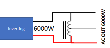
The 6000EX is essentially a 240V HF inverter with an autotransformer to generate the neutral.
1681666883684.png


This is not the same as a traditional low frequency design, but it gives the unit some of the characteristics of a Low-Frequency design. The autotransformer will create slightly cleaner output, and do slightly better at handling short surge loads than the underlying HF frequency that is driving it. The load imbalance handling of the 6000EX is probably better than pure HF architecture, but I don't know if it would be as good as traditional LF architectures.

The large output transformers on the output of LF inverters are better at handling load imbalance, but *ALL* split-phase inverters have limits on the load imbalance. Even the utility transformer feeding your house has limits. You will never get the same wattage on one 120 leg as you can using both legs.

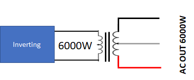
To understand why LF inverters are better at unbalanced loads, lets look at a hypothetical 6000W LF inverter.
1681665733133.png

The Full 6000 W is put into the primary coil of the transformer. If the transformer had 100% efficiency and no resistance, all 6000 W would be available on the 240V wires on the output. However, in the real world with inefficiencies and resistance, not all 6000W will make it through the transformer. The energy loss through the transformer will appear as heat in the transformer. As long as the transformer can dissipate enough of the heat energy, the transformer will not overheat and will continue operating. One of the big factors in the design to handle the heat will be the wire size and insulation on the secondary. Now lets us assume the engineer picked a wire size that exactly matches the need for 6000W at 240V... That means the wire is sized to handle exactly 6000/240=25A.

Now let's look at pulling all 6000 W from one leg of the transformer. This would be possible in the hypothetical loss-less transformer, but reality gets in the way. In order to deliver the full 6000W at 120V, it would have to deliver 6000/120=50A.... but remember the wire was only sized for 25A. So, in my hypothetical transformer with a secondary that can only handle 25A, each leg would be limited to only 3000W before damaging the secondary of the transformer. In real life, the transformers are designed with a safety margin on the capability of the secondary so they can handle an imbalance. How much imbalance is dependent on how much margin is built in. Theoretically, the transformer could be designed to handle the full 6000 W on one leg, but that would get very large and very expensive.

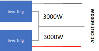
Now let's look at the typical design of a split phase high-frequency inverter:
1681666273512.png

This design can be thought of as two 3000W 120V, 25A inverters in series. In series, they add to 6000W at 240V and 25A.
With this design, only 3000W is available on each leg. In order to get more out of each leg, the inverter associated with that leg would have to produce it. So, in the extreme, if you want 6000W out of one leg, the underlying inverter for that leg would have to be able to handle 6000W..
If you wanted 6000W out of either leg, both inverters would have to be able to produce 6000W, so it would actually be a 12000W inverter.
 
Thanks. This makes sense. So we don’t know the margins but probably not much over 3k.
 
All great info guys. Thanks for clearing this up. With all the inverters out, it was pretty hard to see why the 6000ex is not the go to seeing as it does 240v. Nobody mentions this 3000 watt limitation per leg and if you want to wire up your house or a cabin, you have to be careful with 3000 watts...whereas the 6500 watt all in ones out there don't have this worry...but no 240v. Nobody talks about that. Even Will's review...he never mentions this fundamental limitation.
 
They kind of amount to the same thing. There is a limit of what you can pull on one leg... regardless of the load on the other leg.
I’ve been reading the manual and datasheet for this inverter but can’t find any indication of the max pass-through current.

When in off-grid mode, the fact that you get 25A max output per phase is clear, but the transfer relay is rated for 40A.

They suggest a minimum of 10AWG wire for both AC input and AC output which would be rated for up to 55A in chassis wiring but is only rated for up to 30A when feeding a Subpanel.

With a 40A transfer relay, I’d want wire rated for at least 37A of power transmission on the input, meaning 8AWG minimum or even 6AWG.

With a 30A breaker protecting 8AWG wires feeding transfer switches rated for 40A, you could safely deliver 25A of input power to each phase without much concern of nuisance trips.

I’d think you’d also want 8AWG and another 30A breaker on the AC output to deliver up to 25A of pass-through AC power to each leg.

When the inverter starts trying to offset load using incoming solar power as first priority, it will basically just reduce AC input current and AC output current will remain unchanged.

So as you and others are stating, the 6000EX is 2 x 3000W per 120VAC phase for all practical purposes.

Even protecting it with 30A breakers for 8AWG wire is pushing the rules a bit (should have a 31.25A breaker, which does not exist, to deliver 25A without nuisance trips).

But I don’t see any way to protect it with 35A breakers, even if you could find one and move to larger gauge wiring if needed.

A 35A breaker should have wiring and transfer switches rated for 44A and could avoid nuisance trips and could deliver up to 28A of output power.

Moving down to 25A breakers would not be a recommended way yo deliver 25A of power since nuisance trips would be common.

So 30A breakers protecting wires and components rated for at least 37.5A and delivering no more than 24A of continuous power over extended periods seems like the only option to exploit the maximum power generation capability of this inverter.

I’m looking into one of these to power a Subpanel but my existing Subpanel is on a 50A breaker and 6AWG feeder wiring, so with this inverter looks like I’d need to derate the breaker to 30A…
 
Back
Top