diy solar

diy solar

sol-ark 15 question (bypass wiring)

1201

Solar Wizard
Joined
Feb 1, 2023
Messages
2,506
Location
Texas
I'm investigating a system that can switch between being off grid and being on grid via a transfer switch
I was looking at the sol-ark manual, and where they show a bypass, even in off-grid mode it looks like its still asking for power from the grid.
am I reading this correctly, and if so, why is that? thanks


click the image for an non highligted version as well.
you can also find it on page 9 of 55 of the manual

here
 
Last edited:
I was looking at the sol-ark manual, and where they show a bypass, even in off-grid mode it looks like its still asking for power from the grid.
am I reading this correctly, and if so, why is that?
In my case I use a manual bypass when I need to bypass the SolArk for maintenance, reset or other reasons. I also have a 12k so page 10 in my manual is different.

I am not sure I understand your goal in terms of not using the grid? Have you considered using TOU rates and those settings to control how much grid power you use? I think that would be less complex than programming a switch. I don't use the grid from 3PM until midnight when rates are high and if there is enough solar I charge the batteries from solar. In my case I am also able to sell back to the grid but that might be what is different in your case.
 
Last edited:
In my case I use a manual bypass when I need to bypass the SolArk for maintenance, reset or other reasons. I also have a 12k so page 10 in my manual is different.

I am not sure I understand your goal in terms of not using the grid? Have you considered using TOU rates and those settings to control how much grid power you use? I think that would be less complex than programming a switch. I don't use the grid from 3PM until midnight when rates are high and if there is enough solar I charge the batteries from solar. In my case I am also able to sell back to the grid but that might be what is different in your case.
hi, Im expoloring all my options right now . im just curious why it needs the grid when its in bypass mode.

TOU is why im even looking at this- the utility wants a lot of expensive jumping through hoops to get permitted even though I dont plan to export. if I do a disconnect setup then I am not in parallel to the utility and my equipment never touches theirs so I dont need their blessing. but, as I said I am exploring all the options
 
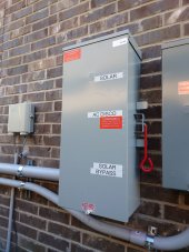
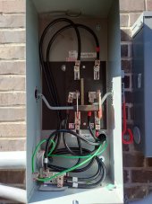
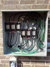
My system is a bit more complicated with two 15K's but the jist is:

Grid/Bypass mode:
-L1/L2/N comes in from grid to the three blocks on the right
-From there it goes to the bottom of the bypass and out through the middle to the main panel

Inverter mode:
-L1/L2/N comes in from grid to the three blocks on the right
-From there it goes to both inverter grid inputs
-From the inverters load output it gets recombined in the blocks on the left
-Then it goes into the top of the bypass and out through the middle to the main panel

Totally stole this off Engineer775 on Youtube by the way...I had to see his video to understand it and even then it wasn't solid until I started labeling distro blocks.

One caveat to understand with this config, the inverter grid input will always be hot unless you throw the fuseable disconnect switch or breaker coming out of your meter. To put it another way...the bypass only bypasses the load side and you'll need to deenergize/safe/isolate the system prior to removing an inverter for maintenance.
 

Attachments

  • Bypass.JPG
    Bypass.JPG
    161.1 KB · Views: 176
  • Bypass Internal.JPG
    Bypass Internal.JPG
    160.6 KB · Views: 187
  • Distro Blocks.JPG
    Distro Blocks.JPG
    214 KB · Views: 179
My system is a bit more complicated with two 15K's but the jist is:

Grid/Bypass mode:
-L1/L2/N comes in from grid to the three blocks on the right
-From there it goes to the bottom of the bypass and out through the middle to the main panel

Inverter mode:
-L1/L2/N comes in from grid to the three blocks on the right
-From there it goes to both inverter grid inputs
-From the inverters load output it gets recombined in the blocks on the left
-Then it goes into the top of the bypass and out through the middle to the main panel

Totally stole this off Engineer775 on Youtube by the way...I had to see his video to understand it and even then it wasn't solid until I started labeling distro blocks.

One caveat to understand with this config, the inverter grid input will always be hot unless you throw the fuseable disconnect switch or breaker coming out of your meter. To put it another way...the bypass only bypasses the load side and you'll need to deenergize/safe/isolate the system prior to removing an inverter for maintenance.
You forgot insulation bushings on your conduit fittings. Since your using tthhn wire.

That grounding bar should have been on the back side hopefully you did not use a self tapper screw. A lot of inspectors would flag it. Which is the same rule on solar mounting rails. Has to be fine thread. Otherwise it doesn't get good contact.
Will Definitely skin the plastic coating off. Insulation maybe if pulled hard enough.

Now that they are already installed and probably not moving anymore?
 
Last edited:
Will Definitely skin the plastic coating off. Insulation maybe if pulled hard enough.

Now that they are already installed and probably not moving anymore?
I'm just posting it's a red flag for a inspector. They would just make you pull it. If they physically saw that. Some of these inspectors don't even actually inspect people's work lately. They might only look at the main hook up at the panel or just sign some papers But if the inspector was doing his job he would red flag it. Only time you don't need the insulation bushings is if you're using service entry wire which has that sheathing over all conductors. Just like Romex wire. Sheathing wire equals no insulation bushings but single conductor wire requires it like thwn ,thhn . Hope that helps. Might as well do it right.
 
I'm just posting it's a red flag for a inspector. They would just make you pull it. If they physically saw that. Some of these inspectors don't even actually inspect people's work lately. They might only look at the main hook up at the panel or just sign some papers But if the inspector was doing his job he would red flag it. Only time you don't need the insulation bushings is if you're using service entry wire which has that sheathing over all conductors. Just like Romex wire. Sheathing wire equals no insulation bushings but single conductor wire requires it like thwn ,thhn . Hope that helps. Might as well do it right.
Oh I’m aware of the codes and inspector propensities.
That’s is PVC conduit / connectors not EMT, RMC or IMC.
Maybe he knew the inspector for that county didn’t require bushing for PVC even though code says bushing unless box provides some way to protect wire.

This also wasn’t his equipment . Just some pictures he pulled from a video on YouTube.

Kinda surprised it passed or maybe it didn’t.
The guy is a pretty large installer on YouTube.
 
Last edited:
My system is a bit more complicated with two 15K's but the jist is:

Grid/Bypass mode:
-L1/L2/N comes in from grid to the three blocks on the right
-From there it goes to the bottom of the bypass and out through the middle to the main panel

Inverter mode:
-L1/L2/N comes in from grid to the three blocks on the right
-From there it goes to both inverter grid inputs
-From the inverters load output it gets recombined in the blocks on the left
-Then it goes into the top of the bypass and out through the middle to the main panel

Totally stole this off Engineer775 on Youtube by the way...I had to see his video to understand it and even then it wasn't solid until I started labeling distro blocks.

One caveat to understand with this config, the inverter grid input will always be hot unless you throw the fuseable disconnect switch or breaker coming out of your meter. To put it another way...the bypass only bypasses the load side and you'll need to deenergize/safe/isolate the system prior to removing an inverter for maintenance.
I using the PDPs just like that on mine.
Replacing 2 Sol-Ark 12ks with 2 Sol-Ark 15s.

Combine both output and input although my input is only 60 amps so not using that large a gauge.
 
Oh I’m aware of the codes and inspector propensities.
That’s is PVC conduit / connectors not EMT, RMC or IMC.
Maybe he knew the inspector for that county didn’t require bushing for PVC??

This also wasn’t his equipment . Just some pictures he pulled from a video on YouTube.

Kinda surprised it passed or maybe it didn’t.
The guy is a pretty large installer on YouTube.
PVC would require a bushing as well. YouTube doesn't make someone a professional. College for the application does but even then you get people that cut corners.
 
PVC would require a bushing as well. YouTube doesn't make someone a professional. College for the application does but even then you get people that cut corners.
I’m aware of that. Depends on when the pictures were pulled from the video pre or post inspection and who the inspector was. You said it yourself, some just look at one thing and go.

Scott (Enginer775)has a licensed electrician with him on the jobs so anyones guess.
 
The switch idea/config/schematic is from Engineer775.

Those pics are from my install done by a licensed electrician who seems to have missed part of code. That said, it was passed by city and utility inspectiors and and I'm not concerned enough to tear it apart to fix what amount to be relatively minor issues.
Yea definitely missed it but doesn’t look like they skinned the cable on the connectors.

I wouldn’t want to pull all those back out to put bushings on the connectors.

I’m in the process of putting in my 15ks.

How do you like them?
You do much selling back to POCO?
 
Last edited:
How do you like them?
You do much selling back to POCO?
Flippin' awesome. (y) The 15Ks capabilities on paper sounded too good to be true...like the straight up marketing hype. Nope! They do everything as written. Running my 4000+ sq ft house with 2 central A/C units no problem (soft starts) with (near) zero grid draw outside of when I have to charge our EV in low sun conditions (I lock out the batteries temporarily and let the grid pick up any deficit).

Loads have gone up this month with A/C use (and we've had a lot of cloudy days) but so far it's going well:
PV Production: 1488 kWh
Load: 1075 kWh
Export: 381 kWh
Import: 63 kWh

Mid-day exporting 14+ kW is common. Daily export record is 80 kWh. ? Fans run on both units throughout but no issues.

July and August will be the test. I think zeroing out will be close.
 
Last edited:
Flippin' awesome. (y) The 15Ks capabilities on paper sounded too good to be true...like the straight up marketing hype. Nope! They do everything as written. Running my 4000+ sq ft house with 2 central A/C units no problem (soft starts) with (near) zero grid draw outside of when I have to charge our EV in low sun conditions (I lock out the batteries temporarily and let the grid pick up any deficit).

Loads have gone up this month with A/C use (and we've had a lot of cloudy days) but so far it's going well:
PV Production: 1488 kWh
Load: 1075 kWh
Export: 381 kWh
Import: 63 kWh

Mid-day exporting 14+ kW is common. Daily export record is 80 kWh. ? Fans run on both units throughout but no issues.

July and August will be the test. I think zeroing out will be close.
You really don’t use much power right now.

We are at 2400 KW in April.

How is your NEMA? What’s the payback?

My array is 19.2kw. Trying to figure out now how to arrange the strings to fit the MPPT.

The setup is similar to the 12ks but not the same.
 
Last July for us was 2730 kWh (2502 w/o the EV) / August was 2633 (2256).

Currently at 1:1 Net Metering within each individual month (no rollover). Rumblings from the electric coop are that they're considering changing. My guess is we'll be going avoided cost structure in the future.

Payback/ROI sucks. High-end batteries/inverters & self-sufficiency in suburbia makes little financial sense. ??? ?

Hey...I can admit it! ?
Yea we are all avoided cost here.

That’s why I don’t participate.

They charge 45 service fee just for the honor of selling back at 2-3 cents a KWH.

My ROI was 10 years. Then I switched to the 15ks but I will also be powering my shop now.

I will have to recalculate but should still be close to 10 years based upon current rates.
That's terrible in northern Minnesota you get paid about 13 cents a kilowatt. No additional fees being connected for solar. Just have your standard connection fee but that doesn't matter being solar or not.
 
Back
Top