diy solar

diy solar

Designing Victron System for Keystone RV Travel Trailer

Ok I've thought about it....

Separate the ac ground from the dc negative busbar in ac/dc distribution panel.
They should be separate from each other and isolated from the frame.
The 12 volt and 24 volt dc_domains are now referenced to the chassis via the lynx busbar.
The multiplus chassis ground lug is connected to the lynx giving a low resistance path for a dc fault inside the chassis.
Also keeps the chassis and ac ground at the same potential.
Also gives an ac hot to chassis fault a path back to the inverter or shore power pedestal.
The idea is the lynx negative busbar is the single point of chassis reference.
I think that covers all the bases.

If anyone else wants to check my logic I would appreciate it.
 
Last edited:
Ok I've thought about it....

Separate the ac ground from the dc negative busbar in ac/dc distribution panel. - done
They should be separate from each other and isolated from the frame. - Currently both bus bars in the power distribution are connected to the shared ground. Why would I want to disconnect the chassis ground from these bus bars?
The 12 volt and 24 volt dc_domains are not referenced to the chassis via the lynx busbar. - Not sure I understand. The 12V is currently referenced to frame via the shared ground (see image below)
The multiplus chassis ground lug is connected to the lynx giving a low resistance path for a dc fault inside the chassis. - done
Also keeps the chassis and ac ground and the same potential.
Also gives an ac hot to chassis fault a path back to the inverter or shore power pedestal. - Where
The idea is the lynx negative busbar is the single point of chassis reference.
I think that covers all the bases.

If anyone else wants to check my logic I would appreciate it.

I don't think I'm following you, but here's what I think you mean? Not sure how the 12V returns to the battery if the 12V bus bar is isolated from the chassis. Wouldn't I also need to run a 6awg from the existing 12VDC bus bar to the lynx?
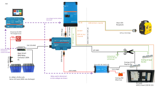
Schematic v11.PNG
 
One question before we get started.
Do the legacy branch circuits have a negative wire or do they all use the chassis for return?

Assuming yes to the previous question.
Your drawing is getting harder and harder to decipher.

The MP2 case grounding lug is attached to the lynx
The lynx is attached to the vehicle chassis as directly as possible with 2/0 awg wire, 2/0 wire is expensive.
The ac out wiring(hot, neutral and ground) to the ac distribution panel is all 10 awg, same as the ac in.
The dc negative between the lynx and the dc distribution busbar in the panel only needs to be 6 awg.

The ac grounding busbar and the dc negative busbar in the legacy panel should be isolated from each other and from the vehicle chassis.

Summary:
The only connection to the vehicle chassis is 2/0 awg directly off of the lynx.
The only connection between the ac and dc domains is the MP2 case grounding lug.
Hope that is clear.
 
One question before we get started.
Do the legacy branch circuits have a negative wire or do they all use the chassis for return?
The legacy DC 12V system has return wires on all circuits which go to a common 12VDC Neg Bus Bar with one exception: The legacy battery negative terminal is grounded directly to the chassis and uses the chassis to return from the 12VDC Neg Bus Bar. (As shown in that image with the floor plan).

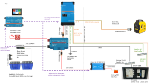
Thanks for sticking with me. I think I understand what you're saying now:
1674075518600.png

The MP2 case grounding lug is attached to the lynx
The lynx is attached to the vehicle chassis as directly as possible with 2/0 awg wire, 2/0 wire is expensive.
The ac out wiring(hot, neutral and ground) to the ac distribution panel is all 10 awg, same as the ac in.
The dc negative between the lynx and the dc distribution busbar in the panel only needs to be 6 awg.

The ac grounding busbar and the dc negative busbar in the legacy panel should be isolated from each other and from the vehicle chassis.

Summary:
The only connection to the vehicle chassis is 2/0 awg directly off of the lynx.
The only connection between the ac and dc domains is the MP2 case grounding lug.
Hope that is clear.
This all makes sense! Does the drawing look accurate now?

This is great, because I already have all the correct size wires running under the trailer for this setup. Will get some build photos up soon, once the 2/0 wire comes in.
 
The legacy DC 12V system has return wires on all circuits which go to a common 12VDC Neg Bus Bar with one exception: The legacy battery negative terminal is grounded directly to the chassis and uses the chassis to return from the 12VDC Neg Bus Bar. (As shown in that image with the floor plan).
Are you getting rid of the legacy battery?
 
I'm disconnecting the house electrical system from the legacy battery, but leaving it installed because it's also used to run the cutaway brakes. (e.g. if the trailer falls off the ball while in motion, it pulls a wire that triggers the trailer brakes).

From what i've read online, other owners have done this when adding solar to this model of trailer with no issues.
 
I'm disconnecting the house electrical system from the legacy battery, but leaving it installed because it's also used to run the cutaway brakes. (e.g. if the trailer falls off the ball while in motion, it pulls a wire that triggers the trailer brakes).
I'm aware.
From what i've read online, other owners have done this when adding solar to this model of trailer with no issues.
Yep.
How are you charging the legacy battery?
 
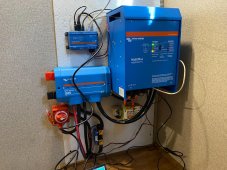
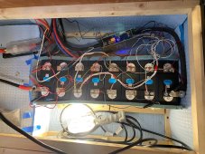
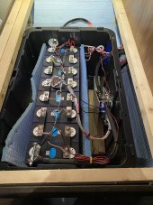
Hey thanks for the help everyone. I've got everything installed and wired up and just getting ready to do a full charge cycle test. Here are some pics (wiring still needs to be cleaned up)
signal-2023-01-29-120459_003.jpeg
signal-2023-01-29-120459_002.jpeg
(It's -14F here, so the light is in the battery box to keep everything warm.)

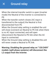
I have a quick question about the ground relay in the multiplus. Should I disable it to prevent a ground loop? Here's the description in the multiplus settings:
1675019572409.png

Thanks!
 
There should be always be exactly one neutral/ground bond.
When you are connected to shore power the bond is upstream of the pedestal.
When you are inverting ac from dc the neutral/ground bond is created by the relay in the Multiplus.
 
Before you hit the road, I recommend that you install strain relief for every wire/cable in that system. The bigger cables especially will use use road vibration to come loose.

Even the cables going into my Cerbo GX have strain relief. The connections to Cerbo GX didn't feel very solid to me, hence the strain relief to make sure the connections stayed connected.

ss6uIGz4sPkuuXR5vmGAiaQajgm2xxp8GzKuqI4EHSkrKycQ7W2KuMSScE7SYuFjaSr6RPjpcjYCYaxKhxw8tmCmTOjyv4Vg6KX6e4wn6a4DTUQypBMwkmpaQK_fnt-CCuj-7Bic4D5uMimbon-dqVlmXxSDOz_VV3fBaKrkiKHjEP1oOEGmPOrue7-46xBJhBHkJl8Kbr4PdWLZ4_JUhDRevSkFtV8FPqtdQz3F4-KDddm-Qa40HshBtJqfKp_lrOFs1cU8aSV7-p4AdBOtIHZNpv1YXhYvbmWDn5FCaYujrvEf5ook3Urlsjd_bVB-rh68tbuxlqPjvFTwaTASGWBV0dEg-JB6xNSsOv0uZr62crnE5Tz0ifR1S8PNGd65rh56oQbT2cBRRAnbydu9kKmXN25_uIX_J9KQmhoDX4Tyx1CKDuImQhpG9bWASZr_uNpqURWCxpUiZWNNhtfOTPmZz7zbK2-wQrlmcbOPMUGvOCBR2l08UnzRmpriGN0xm97rqnG6YGEtY76PL3yuKsxXNxvw3yUdeOs7OA8nKJCYEKEsyVV-ouDjejnV9v9s0qTSrgoa95dq-EwhL8aKawt9_ZV5XQ6qwvAhjZKp80NogmxlNVpjtpZ_WH5HEggu_h4mcX8RV96iJ8z5pB518mf8yshvnQUuRFiEdKiPeyGhOiPALMlLGKUlPf9i6oYOZioc4m-acyFvFFp4iKwmZyg6y_GdzB2jJMtbnE4W-gfmBuY2otWE7xpcmkMuQ6mjCRkWGqXvtP5MTLv1XWUxMdQD1k0XFN_t7dzfgzWOwRRebLSQSNIHRUxOxYP2niBKAMiZYNaT_YodDZo5s9GN_tdxLj-VrUxu7CtFlNI-R_xgIqluiz-Kauv7-ejf1lh_s1VCME0GP3ygmPZSDYZwXbNlu7vC25ctdJZl=w597-h796-no
 
Did you opt for the Victro SmartShunt anyway? Looking at the photo above, it looks like it. I’m building a similar system for my RV and was wondering if the SS provided some sort of functionality you couldn’t get with a BMS tied into the Cerbo. Looks great, thanks!
 
Yeah, I couldn’t get the BMS to talk to the Cerbo. After some testing, it looks like the two disagree on SOC by quite a bit as well. I imagine the shunt is more accurate, but that’s just a guess…
 
Yeah, I couldn’t get the BMS to talk to the Cerbo. After some testing, it looks like the two disagree on SOC by quite a bit as well. I imagine the shunt is more accurate, but that’s just a guess…
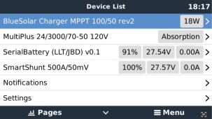
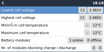
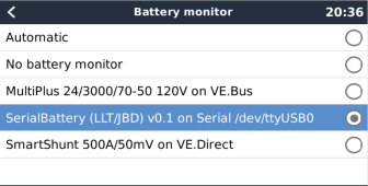
I've got my BMS (Overkill Solar 8S 120A on a 8S EVE280 bank) talking to my Cerbo through dbus-serialbattery. There is a noticeable difference between the two, I've going to investigate further next month (I have a slight battery imbalance that I have to check out as well) but I did notice that the consumed AH was fairly close. I have set DVCC on and set Battery Monitor to use the BMS as the master control so it doesn't try to charge the batteries below 0oC (which happens without the batt heaters on). See attached screenshots... it's in my trailer at the moment (in storage through the winter, so it hasn't seen a load cycle in about 6 months).
1679283155421.png
1679283743697.png
1679283416186.png
 
Yeah, I ended up going with an alibaba BMS and it's so poorly documented that I didn't even want to attempt it. Good job with the overkill solar hack though!
 
Yeah, I ended up going with an alibaba BMS and it's so poorly documented that I didn't even want to attempt it. Good job with the overkill solar hack though!
Thanks, I'm still chasing the problem with the difference between the two, it seems they are off by about 0.1A.

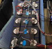
I glanced back at your battery photo, are you tapping a 12V connection off your cells here? 1681397677343.png
 
What about power tongue jack? Running off the old FLA 12v? The 7 pin charging that battery only does it last sitting for 2 weeks...most don't none ever have had. I would have went straight from the dc-dc 24 to 12 converter to the factory wiring on the tongue and dumped the FLA myself.
Tow vehicle via the aux power pin on the trailer 7-pin
 
What about power tongue jack? Running off the old FLA 12v? The 7 pin charging that battery only does it last sitting for 2 weeks...most don't none ever have had. I would have went straight from the dc-dc 24 to 12 converter to the factory wiring on the tongue and dumped the FLA myself.
An FLA should only lose like 3% a month if no loads. Are you thinking the tongue jacks consume power when not in use or something else?

I have an enclosed trailer i take maybe once a month I added an electric tongue jack, lights and a 100ah SLA battery. Mainly worried about leaving lights on and draining battery, didn't think about the jack using idle load. My idea was to use some device that'll cut voltage off when it's like 12.65v (80%) incase I forget to turn lights off
 
I'm not aware of a tongue jack having an idle consumption. My Husky tongue jack is rated for 25 amps, but I've never tested that.
 
An FLA should only lose like 3% a month if no loads. Are you thinking the tongue jacks consume power when not in use or something else?

I have an enclosed trailer i take maybe once a month I added an electric tongue jack, lights and a 100ah SLA battery. Mainly worried about leaving lights on and draining battery, didn't think about the jack using idle load. My idea was to use some device that'll cut voltage off when it's like 12.65v (80%) incase I forget to turn lights off
No I didn't mean the power tongue jack has an idle consumption whatsoever I meant using that and breakaway only for the FLA and it never getting a charge other than from the 7 pin...In my 24 yrs of owing RVs I've never had an FLA sit idle for more than 2 weeks without needing a good full charge. Whether they were new or old I've had them all Interstates, Deka's, East Penn, etc etc and that's with taking the best care of them as well. To me in 24 yrs all FLA's are garbage and with your system I'd just dumped it and tied it all together like most do...but hey to each there own.
 
No I didn't mean the power tongue jack has an idle consumption whatsoever I meant using that and breakaway only for the FLA and it never getting a charge other than from the 7 pin...In my 24 yrs of owing RVs I've never had an FLA sit idle for more than 2 weeks without needing a good full charge. Whether they were new or old I've had them all Interstates, Deka's, East Penn, etc etc and that's with taking the best care of them as well. To me in 24 yrs all FLA's are garbage and with your system I'd just dumped it and tied it all together like most do...but hey to each there own.
99% of trailers with electric brakes only have a mini sla battery that just charges off the 7 pin including those with a power tongue jack. Not travel trailers but just everyday flat or enclosed trailers. If your chassis battery isn't lasting more than a couple weeks you have something else connected to it draining the load. It's not an issue with FLA it's an issue with whatever is pulling a load when off
 

diy solar

diy solar
Back
Top