diy solar

diy solar

Series string shading summed up in 4 pictures

In the arrays constructed here, how are the bypass diodes arranged? In my testing (with a far smaller number of panels) I found that different shade patterns had wildly varying impacts depending on how the shade crossed PV cells that were covered by the same bypass diode.

(edit)
I was thinking about this more last night as what is observed here doesn't make sense to me given what a bypass diode would do. One thing that occurs to me is that your array is much larger than the 2-panel arrays that I used in my testing. That means that when the bypass diode kicks in, it will be carrying a lot more power. Is it possible that the bypass diodes in the shaded panels have become damaged? If one hooks up a volt meter across the shaded panel, what sort of voltage drop is seen? If the diodes are working properly, the voltage drop should be close to zero. Also current going into the shaded panel should be about the same as the current leaving the shaded panel. From an electrical perspective, the shaded panel should look the same as a simple wire. If it isn't that would suggest that something is wrong with the bypass diodes.

(edit2)
Sorry to keep adding on, but I think I just realized where the difference lies. It comes down to size. My test scenario used a tiny 2-panel array. Your arrays are larger - looks like 10 panels in series. The issue is whether the bypass diodes in the shaded panel remove the entire panel from the series, or just some of the cells in the panel. If the shade covers all the bypass strings in the panel, then the panel is effectively completely removed from the array and power drops by the proportion of lost panels. In a 2-panel array, losing one panel results in a 50% power reduction. In a 10-panel array, the power reduction is 10%. But if the shade only covers some of the bypass strings in the panel, then the panel is still in the series, but with a reduced number of PV cells, which means a reduced amperage. So if the shade removes 1 of 3 strings in a panel, then the amperage is reduced by 33%. Since serial arrays rely on having consistent amperage across all panels, reducing amperage in one panel by 33% reduces the amperage across the entire array by about 33%. In a 2-panel system, a 33% reduction is smaller than the 50% reduction for losing an entire panel. But in a 10-panel serial array, that 33% reduction across the array is a much larger impact than the 10% reduction for completely losing a panel.

This would tend to suggest that for larger arrays there is a clear advantage for parallel configurations. As long as the shaded cells receive enough light to stay close to the nominal Voc (about 200 W/m2 from what I can find in the online literature) then a partially shaded panel would maintain about the same Voc and simply produce less current. In a larger parallel array, as long as each panel is producing about the same voltage a reduction in current from one panel has a much smaller impact on the entire array.
 
Last edited:
Would be nice for someone to post their evidence of series string being better than parallel configuration for shading. Please challenge my position! I have done this test many times now and the results are the same everytime. I even covered this in older solar panel test videos. Same results, every time.

OK, I'll do it again.

Years ago someone came to our company pitching optimizers.
I asked about diodes, he said they can't handle the current (underrated part.) So how come optimizer can handle full current??

I went home and shaded one panel of 9s2p array. Think I got about 17/18ths of full power (but sun was variable, so not a controlled test.)

I'm guessing your shade allowed small amount of current, and MPPT failed to find lower voltage much higher peak.
Every figure out why you got 2000W later, after 200W the first time?

How long have those end panels had to deal with such hard shading?
It places extra stress on the bypass diodes. Perhaps they are toast?

One of my thoughts.
Some brands, explicitly only for sun at an angle, well below full current.

Some thermal imaging perhaps, or other testing of the end panels to check their condition would be interesting.

If current forced through PV cells (diode open), high voltage across it and heated up.
But Guppy diagnosed otherwise based on volts and amps.

What I see is you have identified an issue, you haven't shown what the cause is, but are assuming it is the bypass diodes not working as expected. Based on the fact the voltage is so high, I would challenge that conclusion. if they the diodes were not present, you would have very low voltage.

To expand further, you have some device, it is job is to load the array to extract maximum power. In the case of shading, you get what is referred to multi-hump mppt and I suspect, your charge controller doesn't have the code to deal with this situation.

Most likely.

I think half-cut panels will be much more likely to cause this. Nice firm 1/2 current when part is shaded.

I'm curious of examples of MPPTs that do handle this situation properly

Any SMA grid-tied string inverter.

I heard it, but I'm honestly a little surprised the MPPT didn't pick up the peak power at the lower voltage. I've seen these things do sweeps every 10 minutes or so. I just don't know if the sweep progresses low enough to capture the higher output at the lower voltage.

MPP, I'm thinking.

You don't suppose our Will was a little impatient?

Yes, cable to concrete anchor. ... I bought a nice hammer drill so I have been trying to find every excuse possible to use it haha

I suggest setting female threads flush with the pavement.
Lots of facilities, I see left over bolts cut off with a grinder. Then next time would have to set a new one.

Yes!! They make such great tools. It makes my life 100X easier. Planning to re anchor my gate openers this week ?

When I was growing up, Milwaukee was big, but as a rental tool repair guy I had to replace smashed spring activated hammer mechanisms occasionally. Bosch had shown up, and their piston/air systems were quite reliable. (Skill did something similar, but always breaking.)

I have an old Milwaukee 5300 rotohammer (and other tools.) Also Bosch Brute 60# hammer. I picked up a Bosch roto hammer when I couldn't get Milwaukee hex drive bits anymore.

So Milwaukee is back to being a premium, reliable model now?
 
So Milwaukee is back to being a premium, reliable model now?
I would consider Milwaukee as being top-tier now. They have some seriously quality stuff.

I'm stuck with Ryobi, just because I'm so deep into the amount of batteries and tools I already have. Its hard to switch.
 
I just remembered - I did perform this test recently.
It was last month, shortly before I shocked myself silly at work.

8s2p SunPower 327W single crystal panels.
SMA Sunny Boy 8000US transformer type grid-tied PV inverter, PV array positive grounded.

Shading one panel, I got 3% less than 15/16ths of unshaded array.
I was running back and forth to snap photos of setup and inverter display and DMM. MPPT response was plenty quick.

It seems we're each correct about our experiences with our equipment.
I think if you get more than a few percent penalty with partial shading (beyond expected power loss from fully or partially shaded section), that means your MPPT isn't doing its job. Now if the string is relatively short so a large percentage is shaded, the unshaded string does get pulled far from maximum power point, so that is to be expected; check the power/volts curve. I'm seeing 13% of a string shaded being only 3% penalty.


I would consider Milwaukee as being top-tier now. They have some seriously quality stuff.

I'm stuck with Ryobi, just because I'm so deep into the amount of batteries and tools I already have. Its hard to switch.

Oh, cordless. I do have a few of those now.
Most of my tools are 120VAC, 15A. Hammer drill, jackhammer, grinder, pipe threader, conduit bender, cable tugger, etc.

Can you explain why

Shingled panels are internally arranged something like 62s10p (more or less), so shading on a side leaves most of the current available.
Extreme version of "half cut"
 
Last edited:
Each row is a string. These two strings of panels are in parallel and connected to victron MPPT. You can see that the last panel is shaded:
View attachment 140972

View attachment 140974

420VDC. So plenty of voltage and the last panel in the string is shaded, but only producing 200W for both strings!

Now wait 30 minutes..

The shading is now gone, and we have power!
View attachment 140975
View attachment 140976
2465 Watts! The moment the shading was eliminated, the power jumped 10X!

You would think that the bypass diode would do a better job on either string, but it doesn't.

This was discussed in another thread about shading. In my tests over the years, the bypass diode really doesn't help that much. Usually my output drops significantly if any of the panels are shaded. This is why parallel connection does significantly better when you have shading issues.
It seems that the MPPT's algorithm falsely locked to a local optimum point on V-I curve instead of a global optimum that is at much lower voltage (less shade panels). Perhaps other brands MPPT might not experience the same problem. My SMA inverter doesn't have this problem. I can try this situation on Growatt inverter.
 
A great test for Tigo optimizers. I don’t know if they are worth it for when there’s 100% full sun, do they have losses?
 
A great test for Tigo optimizers. I don’t know if they are worth it for when there’s 100% full sun, do they have losses?
I have Tigos and can confirm. If I 100% shade 1 panel in an 11s string, the other 10 show no drop in output.
 
Great, a highly valid person’s opinion has them. I’m just wondering if you have two identical arrays in full sun, no shade one with and the other without Tigos, is there a loss having the device on the system? Or is it negligible? Or you haven’t been able to compare?
 
Great, a highly valid person’s opinion has them. I’m just wondering if you have two identical arrays in full sun, no shade one with and the other without Tigos, is there a loss having the device on the system? Or is it negligible? Or you haven’t been able to compare?
I haven't been able to compare, all 44 panels have optimizers. The Tigo app does show "reclaimed" energy that would have been lost due to shading or panel mismatching. It usually is in the 10-20% range every day. It definitely makes a difference in my scenario.
 
@Lt.Dan

It sounds like you are happy with them. From the sound of it, you get all the benefits of panels being paralleled singly, with the ease of them being in series for wiring. Have you had any fail during your time with them?
 
Great, a highly valid person’s opinion has them. I’m just wondering if you have two identical arrays in full sun, no shade one with and the other without Tigos, is there a loss having the device on the system? Or is it negligible? Or you haven’t been able to compare?
Unfortunately, that is next to impossible as even if they are same panels / quantity's, the variations in individual panel can be more than the expected improvements the optimizers can provide.
 
I’ve got running data on my system. I may bite the bullet and see what’s what. Just wondering out loud, I wonder if the diode could be eliminated for even better efficiency with an optimizer?
 
Great, a highly valid person’s opinion has them. I’m just wondering if you have two identical arrays in full sun, no shade one with and the other without Tigos, is there a loss having the device on the system? Or is it negligible? Or you haven’t been able to compare?
Negligible loss when there is no shading.

No gain when there is full shading of one or more panels.

Optimizers only make a difference when you have partial-width shading of one or more 1/3 panel subsegments (enough shading to reduce current through the partially-shaded subsegment without cutting off current flow entirely).

Optimizers can also help if you have mismatched panels in the same series string or mismatched string lengths in parallel under the same MPPT.
 
Bypass diodes only conduct when the solar is blocked in the series of cells, in normal operation they are in effect not part of the circuit, with or without an optimizer attached

Subsection completely blocked (no current output) or partially-blocked enough to reduce current for the entire string enough such that bypassing that entire partially-blocked subsection (meaning reducing string voltage by 1/3Vmp + 0.6V) translates to higher power output (at least assuming you’ve got a good MPPT).

So a bypass diode will activate whenever:

Imp x (Vmp x [S - 1/3] - 0.6V]) > Ishaded x Vmp x S
 
Another way to explain this is.
Bypass diodes are in parallel with sub sections of the panels. They aren't part of the circuit. Until the sub section becomes more of a load (extremely shaded or failed) than a power producer. Then the Bypass diode becomes the path of least resistance. (Which electricity always follows)
 
What I would like to know is how much power was being dumped into the shaded panel. A good IR imager would of been handy to compare the panels in shade vs sun. I bet the shaded panels where hotter.
 
It seems that the MPPT's algorithm falsely locked to a local optimum point on V-I curve instead of a global optimum that is at much lower voltage (less shade panels). Perhaps other brands MPPT might not experience the same problem. My SMA inverter doesn't have this problem. I can try this situation on Growatt inverter.
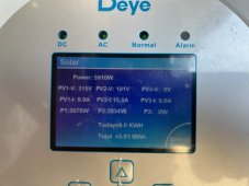
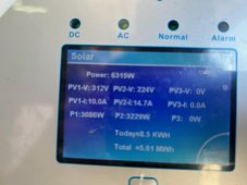
Did a simple shading experiment on two inverters today: One is Deye 16K and the other one is Growatt. Got two drastically different result. Here is the setup and the result

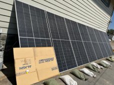
8 panels on Deye with one partially shaded
IMG_2874.jpg
Deye's MPPT understands that one panel is out and drop the operating voltage from224v to 191v (one PV worth) while maintaining the same current, resulting in only 1/8 power drop
Note: shading experiment is done on PV2 shown in the photos below.

IMG_2873.jpgIMG_2870.jpg
Growatt MPPT acted differently
one of 6 panels was shaded
and the mppt confused and increased the operating voltage (instead of dropping the voltage by 1/6 of the unshaded)

resulting two panel worth of power drop
Voltage 171v --> 183v
power 2383w --> 1577w (2/6 drop instead of 1/6)
 

diy solar

diy solar
Back
Top