diy solar

diy solar

MC4 Questions

Westy Travels

New Member
Joined
May 23, 2020
Messages
1
Two questions:

1) In Will's book, he says on page 63, "It is preferable to have all MC4 connectors and branch connectors located on the roof. MC4 connectors should never be inside your vehicle." (Italics are mine.) Why? Will doesn't say! He just says NEVER.

Why can't I have a short dongle coming from my Victron solar charge controller and just snap in the MC4 connectors to whichever solar panel I want? I have two solar panels: a glass 100 watt Renogy on the roof of my VW Westfalia and a collapsible 110 watt panel from GoWesty that forced me to buy a Greeley SAE to MC4 connector. Having the MC4s in my van works well for my dual setup, especially with the Greeley dongle that I can switch in or out depending on which panel or panels I'm running.

2. I haven't heard anyone say it's bad to daisy chain MC4 connectors. I have the Renogy MC4 connectors on the back of the panel, Windy Nation 40 foot 8 AWG line with MC4 connectors on both ends, and then the Greeley with MC4 connectors in the van. That's a lot of connectors. Bad idea to daisy chain?

Thanks for any constructive input on one or both issues!

--Mark
 
MC4 connectors, all connectors really, have resistance. The more you put in line, the more resistance but decent MC4 connectors are under 10 milliohms so unless you go nuts or use inappropriately rated MC4 connectors, resistance is not going to be an issue. If you look at the specs for most panels you will see 600VDC/1000VDC (different test standards, but they mean the same thing) as the max voltage. With a 24V class panel, Voc might be 42V. That means you can string about 24 of those panels in series (electrically speaking, local regulations may prevent you) so you can see that there's no problem with a heap of connectors in series so long as the current is within spec.

Use good connectors rated to handle the current you are putting through them and you will be OK.

You shouldn't use the MC4 connectors as a way of breaking the PV as disconnecting them live will draw an arc inside the connector where you can't see it and that will degrade the surfaces and push the contact resistance up with each arc, potentially causing heating of the connector next time you use it. Use a suitably rated breaker / isolation switch to disconnect the array or throw a blanket over the panels failing that.
 
Question #1:
Was asked and answered here and here.

Short answer, it doesn't really matter and I don't think Will intended that phrase to come off as a rule (it definitely sounds like one based on the wording). But making your connections on the roof = less wires going through the roof and a smaller entry hole.
 
Help please. I have one run of 15 foot PV 10g wire going directly from branch connector to mpp solar and it’s working fine.

However, I initially had an extension PV cable between the two to allow me to move the panels an additional 10 feet if needed, and an additional 20 ft with another extension chord. I was getting zero voltage after connecting the extension. I tested all the cables and mc4 connectors and all worked if coming directly out of the panels. I’d get zero voltage when I’d connect the additional extension wire.
I even tried crimping an mc4 on a 10cm 10g wire connecting it then testing it and would get zero voltage. The 10cm would get voltage directly off the panels.
It’s fine now, but would be nice to utilize the cable now rather than buy raw wire to crimp mc4’s too.
 
I personally wouldn’t use MC4 connectors anywhere. But if you are happy with them as a connector, it doesn’t matter where you use them. Some charge controllers have MC4 connectors as their input connector.
 
I personally wouldn’t use MC4 connectors anywhere. But if you are happy with them as a connector, it doesn’t matter where you use them. Some charge controllers have MC4 connectors as their input connector.

So what do you use? Do you cut them off your panels and solder wires together?
Help please. I have one run of 15 foot PV 10g wire going directly from branch connector to mpp solar and it’s working fine.

The way you describe it, the the extension wire is bad.

I'd start by looking at the pins inside the cable. Not MC4, but other pinned cables I'd work on would have pushed or bent pins. In an old job, really hated when it was a 100 pin connector, and all pins needed to swapped to a new one.

I have an MC4 crimper off Amazon for $15, spare MC4 connectors, wire cutters, and wire strippers, my next step would be to cut off both ends and then put a new MC4 connector on to see if it fixes it.

Ohming these cables to check for continuity is a good first step, but the multimeter will still see 0 ohms and beep if the wire is only holding on by a single piece and all the 99 others are broken, but when hooked up, it won't work right.
 
If you aren’t going to disconnect the panels in their lifetime, it makes more sense to direct crimp and cover with adhesive filled uv stabilised heatshrink rather than use a MC4
 
Many solar panel providers will void any warranty if you cut the mc-4 connector from the panel. My four connectors have worked flawlessly on the roof of my van. Going on 3 years on the road.
 
So what do you use? Do you cut them off your panels and solder wires together?


The way you describe it, the the extension wire is bad.

I'd start by looking at the pins inside the cable. Not MC4, but other pinned cables I'd work on would have pushed or bent pins. In an old job, really hated when it was a 100 pin connector, and all pins needed to swapped to a new one.

I have an MC4 crimper off Amazon for $15, spare MC4 connectors, wire cutters, and wire strippers, my next step would be to cut off both ends and then put a new MC4 connector on to see if it fixes it.

Ohming these cables to check for continuity is a good first step, but the multimeter will still see 0 ohms and beep if the wire is only holding on by a single piece and all the 99 others are broken, but when hooked up, it won't work right.

Thank you for the suggestions. However, as described above, I get around 33v on all cables if connected directly to the solar panels mc4 connectors and testing with multimeter. This includes the extension cables and the small mc4 connection I made. As soon as I connect an additional mc4 connected cable to the cable that would then run to the mpp I get 0 volts at the end of the extension cables. All cables have mc4 connections btw except one which is a 15 ft cable that has mc4’s on only one end so the other can go to my mpp. I’m using that one now and it’s working great, I’m just limited by where the panels have to be to reach the mpp. I’m saying this to avoid confusion. I can rearrange all the cables i have in any fashion and all will get 33v on multimeter as long as I don’t connect another mc4 connected extension run. If I could just connect one 10 foot extension with mc4’s or two to get twenty feet I’ll have more sun to play with when settled in different locations. I can’t though because as soon as I try that, regardless of which cable is connected to the branch connector from the solar panel I get 0 volts. I tested it with all possible variation of connecting the three sets of cables I have (2 10 ft 1 15 ft) and the small one I crimped for testing purposes. Make sense? It doesn’t to me. I can’t image the resistance be anywhere close enough in multiple mc4 connection to get a 0v reading. I must be missing something. I’m new at this and it’s probably something basic that I’m missing or don’t understand. Maybe I’ll test it again and see if it works. I was only getting like 25 watts out around dusk when I was doing this but I don’t think that long runs of wire would result in zero wattage with conditions of minimal current. I’ll test midday and see if that’s it though.

BTW I have 2 365a Renogy’s in parallel using a 30a branch connector. I just purchased a 50 amp one for if I pull at its capacities wattage.
 
Last edited:
You have a bad cable or connection. Bad crimp? First check each mc-4 extension cables for continuity.
 
No that’s not it as explained above. I explained in detail that that was the first thing I tried. I thought maybe a bad crimp too but have tested on wire with no mc4 at end. The one10 ft I crimped female on female and male on male as extension cord but I tried with the precrimped 15ft and raw end of the 10ft and got zero volts they were connected and 33 when trying directly to branch connector.
 
Even though it might seem insulting if you have made up your own leads is it possible you have managed to reverse the plugs so that you have one or more panels reverse wired in the array? Extension leads are always male - female unless you have customised your cabling somewhere else to compensate.

Even a moving needle meter should show some voltage even if there is a high resistance point in the overall wiring. To read 0 volts with the array not connected to the charger says, full open circuit which might be bad crimp, defective MC4 connector where the metal inside the connector does not make contact at all with the connector's mate, break in the cable; or it says short circuit; or is says there is no voltage going in at the far end to start with ie incorrectly wired panels etc.

*edit to correct many, many typos etc*
 
Last edited:
In my first attempt to make MC4 connections on my PV wire I got it wrong at least twice. Fortunately, only once did I have to cut off a connector. I had to put tape with + and - on it to make sure I didn't screw it up again.

I would use the continuity feature on my voltmeter to verify that the connections are correct. Then I would use the voltmeter to make sure that the expected polarity is coming out of a connector. If you're getting zero volts at the end of an extension then you have a bad wire, bad connector, it's dark out, or you have the voltmeter set to AC instead of DC.
 
I initially purchased two 10ft cables that had mc4 connections on one end only . I wired one set of them with the m mc4 connected to positive of charge controller and f to negative and then labeled the wiring with red and black tape( red for m and black for f) I realized after the fact I did this labeling and wiring wrong because as you mentioned there’s one m and one female on extension chords and I needed the running end relative to charge controller to be f not m. This wasn’t a problem though since my other 10ft wire needed to have an mc4 crimped to make the connection. Therefore I ended up with a male male (which was a negative extension wire) and female female ( which was a positive) extension chord. I was very careful in making sure I didn’t reverse anything.
I then bought 15 ft extension cable because of the zero voltage problem and the 10 ft already wired wouldn’t reach my panels. Before I ran the 15ft that I ended up cutting the ends off of to hook to panel I tested everything as described above.
This was the definitive test: I cut about a 2 inch piece of wire from the 10ft cable set that had no mc4 on the end which was wired to controller and crimped mc4’s to those. I then plugged them into the branch connector coming from the panels. This read 33v on multimeter. I then did the same thing with the 15 ft extension cable (m f and m f ends) that was never tampered with cut or anything. This also gave me 33v off branch connector. I then simply left the 15 ft cables connected to branch connectors and plugged in the mc4 connectors that I crimped for testing. This gave me zero volts after the connection when placing on the raw end wire which previously gave me 33v when coming directly from solar panel branch connector.
All the crimping ends of extension wire I’ve tested directly off solar panel branch connector and get 33v in until I simply add another cable via mc4 connection at the end. Maybe the mc’4’s are incompatible? No, because the two 10 foot ones are the same exact cables with prefabricated mc4’s and the same exact thing happens when I test those in the same fashion as described above. Maybe the crimp is bad on m m and f f and the short run one such that I get voltage directly off branch connector, but no voltage when I connect it to the other 10ft cable. I’m pretty sure I tried to connect the untampered 15ft cable with the untampered 10ft cable and got zero volts
 
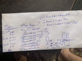
I think it may be beneficial for you to draw a schematic of exactly how you have things wired, and not from memory either, physically trace the wiring and draw it exactly as observed. If you don't draw it exactly as observed you may hide the problem. Once you have it drawn, post that to the forum so other's can have a look at what you actually have.

A picture can paint 1000 words.
 
What mistake?
Am I wrong in my thinking that the wire and connections are all just metals that need to come in contact to conduct. The male and female and color codes are jus a way to insulate and protect from short circuit and know which is which as to also not short circuit by reversing connections?
 
Back
Top