TLDR: inverter wired to opposite terminals than rest of loads/inputs on a dual battery setup. Scream foul?
I have a long list of poor decisions I’ve inherited from a well-regarded van building company in a van I purchased from them back in July, and would love some help fixing them!
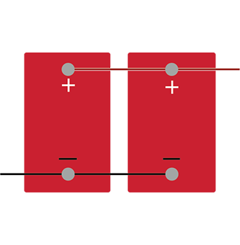
First off, something I cannot seem to find an answer for anywhere: the system has two li time 200ah batteries wired in parallel, with DC loads and charging inputs on positive of battery no.1 and negative of battery no.2, but the inverter is hooked up to negative of battery no.1 and positive of battery no.2
Is this a big no no? Or should it be fine? It certainly isn’t how I would’ve done it!
(For those curious, I’m still trying to work with company to try and fix the errors so I’ll refrain from naming them for now)
(Never mind the li time battery bms cannot support 3000w, that’s another issue that is hopefully getting solved by the van company by dropping in the ‘plus’ version of the battery with better bms. Oh and the breaker is too small, no bus bars, no battery monitor, undersized cables, no master switch, cheap breakers instead of fuses, unprotected wires, loose connections, wrong charging settings… nightmare fuel!)
Full equipment list:
2x li time 200ah batteries in parallel
3000w Renogy inverter
Renogy Rover Li MPPT
Renogy 40a DC to DC
400W of solar
thanks in advance and sorry for the long read!
I have a long list of poor decisions I’ve inherited from a well-regarded van building company in a van I purchased from them back in July, and would love some help fixing them!
First off, something I cannot seem to find an answer for anywhere: the system has two li time 200ah batteries wired in parallel, with DC loads and charging inputs on positive of battery no.1 and negative of battery no.2, but the inverter is hooked up to negative of battery no.1 and positive of battery no.2
Is this a big no no? Or should it be fine? It certainly isn’t how I would’ve done it!
(For those curious, I’m still trying to work with company to try and fix the errors so I’ll refrain from naming them for now)
(Never mind the li time battery bms cannot support 3000w, that’s another issue that is hopefully getting solved by the van company by dropping in the ‘plus’ version of the battery with better bms. Oh and the breaker is too small, no bus bars, no battery monitor, undersized cables, no master switch, cheap breakers instead of fuses, unprotected wires, loose connections, wrong charging settings… nightmare fuel!)
Full equipment list:
2x li time 200ah batteries in parallel
3000w Renogy inverter
Renogy Rover Li MPPT
Renogy 40a DC to DC
400W of solar
thanks in advance and sorry for the long read!