diy solar

diy solar

Battery Over-discharged error on Renogy setup

jajao555

New Member
Joined
Dec 31, 2023
Messages
4
Location
Baltimore
I've been having an issue with Battery Over-discharged errors. The last two times it's happened I've been using the van for about a week usually just the cooler running 24/7, a laptop using the AC outlets during the day, occasional phone/device charging, and a toaster once or twice over the week. Both times it happened at the end of the week if that helps with context.

Basically no issues all week then around the end of the week inverter starts beeping, I lose power, check MPTT and see the E1 error. I turn everything off and the batteries eventually re charge and everything is ok.

The system is in a converted Sprinter van with 4 Renogy 100W panels, 3 100ah LiFePO4 batteries, and a Renogy 40A MPTT. No connections to vehicle or inputs for campground power.

I found the the previous owner hadn't set the batteries to Li and it was on the default lead battery type. I hoped changing it to Li would resolve it but I just had it happen again after correcting the battery type about 3 weeks ago.

I had also bought the Renogy bluetooth monitor for the MPTT to help troubleshoot but I didn't find anything obvious now that it's happened with the BT monitor installed. The Renogy MPTT shows the error as well as the Renogy bluetooth monitor.

I plan on changing the wiring to fix it so its better for current sharing. I should move the positive to the top positive battery terminal correct? Not sure if that would resolve the over-discharging issue?

I get 12.9V from the bar terminals the batteries are connected to in the current setup. They've now been charging with no load for about 3 days with no load and the error has cleared now.

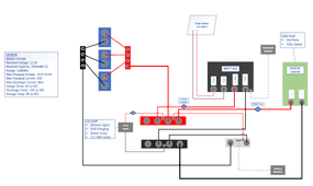
Here's a diagram I made of the setup:
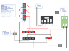
Screenshot 2023-12-29 143612.png

The battery monitor is this one from Renogy. It does not show any errors or even that the batteries are depleted. It always shows the batteries at 100% so not sure how accurate it is or if it isn't connected correctly?
https://www.renogy.com/500a-battery-monitor-with-shunt/

This is the bluetooth monitor if it helps
https://www.renogy.com/bt-1-bluetooth-module-new-version/

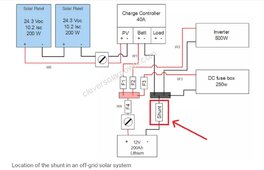
I'm sort of confused on why the bluetooth monitor doesn't show any load statistics. The load terminals aren't used off the MPTT so I'm guessing that's why? The example diagram Renogy provides actually has it wired how the PO did it, where the inverter and DC load is directly off the batteries. Also in the manual it says the load terminals on the MPTT can't handle more then 20A. So I'm not sure if that's the actual use case for those load terminals?
https://www.renogy.com/template/files/pics/200_watt_premium_kit_rover_bt_1.jpg
 
Any chance the shunt is connected backwards? Does it show its charging when it should be showing discharging and vice versa?
 
What makes you think you HAVEN'T run your batteries down?
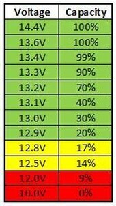
1. You say you measure 12.9v when testing the bar terminals. You also said after 3 days charging, but unclear if 12.9v before or after charging. In any case, that is like 20% charge remaining for LifePO4. Close enough to empty that it makes me question it.
msf4vpdl-1_14.jpg

2. You didn't say what the temperature of batteries is, could you be running into a 0c charging cutoff? Are they near freezing?

3. If your battery monitor shows 100% charge at 12.9v, it is obviously not working correctly.
4. You state you are using inverter, and running toaster and AC outlets. You do NOT say inverter is disconnected when not in use... the parasitic draw of a 3000 watt Renogy inverter as an example, or no load current draw, is 32w. That will drain 3 100AH batteries, 3840wh, in 120 hours just sitting there, 5 days.

All this adds up to my suspicion: your panels are not supplying as much power as you are using. Your inverter is constantly draining them, as well as your various uses. After several days, they are out of power. Everything is working as it should except,
--your battery monitor is faulty
-- your pv panels dont supply enough watts, or are not properly matched to your mppt.
 
I should move the positive to the top positive battery terminal correct? Not sure if that would resolve the over-discharging issue?
Yes, this could help significantly. There is a good chance that your top 2 batteries do not get much current flowing as the path of least resistance is the lowest battery.

They've now been charging with no load for about 3 days with no load and the error has cleared now.
When you disconnect to rewire, check the resting voltage of each battery after they've sat for a while. If you see a significant difference, you'll know this was an issue. If you were able to charge to completion with a significant absorb stage, there may be less of a difference.

I agree with others' opinions that you've run your batteries low.
 
Yes, this could help significantly. There is a good chance that your top 2 batteries do not get much current flowing as the path of least resistance is the lowest battery
It will be an improvement, but the middle battery would still contribute less. Running equal lengths of wire for each battery to a common point, for negative and positive separately of course, would be the easiest way to get the most equal contribution of the batteries.
 
It will be an improvement, but the middle battery would still contribute less.
Agreed.
There is a great discussion of the here (this is the 3 battery calculation). Read the first 4 posts for a great explanation of the concept.

Running equal lengths of wire for each battery to a common point, for negative and positive separately of course, would be the easiest way to get the most equal contribution of the batteries.
Yes, it usually is, though i have never done this for various reasons.
 
Thanks for all the input! Lots of good info and stuff to look into.

Any chance the shunt is connected backwards? Does it show its charging when it should be showing discharging and vice versa?
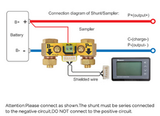
I just double checked it and it looks like its connected correctly. The battery negative goes to the B- side and the P- connects up the the negative bus to the MPTT.

Screenshot 2023-12-31 161147.png

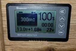
Here's a pic I took just now. So it sees it as charged full but I'm thinking its just not been setup properly. I think I'll have to run the batteries down to reset it after reading the manual again. It actually wasn't working when I got it the PO had flipped wires in the connector in the shunt side for some reason and it wasn't even powered. After getting it powered I thought I could just set the Ah capacity and it would work but it sounds like it needs to be depleted then charged for it to read properly. So I'll come back to that issue later I guess.
20231231_151819.jpgScreenshot 2023-12-31 164519.png

What makes you think you HAVEN'T run your batteries down?
1. You say you measure 12.9v when testing the bar terminals. You also said after 3 days charging, but unclear if 12.9v before or after charging. In any case, that is like 20% charge remaining for LifePO4. Close enough to empty that it makes me question it.
View attachment 186032

2. You didn't say what the temperature of batteries is, could you be running into a 0c charging cutoff? Are they near freezing?

3. If your battery monitor shows 100% charge at 12.9v, it is obviously not working correctly.
4. You state you are using inverter, and running toaster and AC outlets. You do NOT say inverter is disconnected when not in use... the parasitic draw of a 3000 watt Renogy inverter as an example, or no load current draw, is 32w. That will drain 3 100AH batteries, 3840wh, in 120 hours just sitting there, 5 days.

All this adds up to my suspicion: your panels are not supplying as much power as you are using. Your inverter is constantly draining them, as well as your various uses. After several days, they are out of power. Everything is working as it should except,
--your battery monitor is faulty
-- your pv panels dont supply enough watts, or are not properly matched to your mppt.
Not sure if I miscommunicated somewhere but I wasn't trying to say it wasn't a battery being run down issue. I figured that's the issue but I don't know enough on how to troubleshoot why it's happening lol.

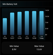
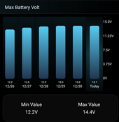
1. I turned everything off on 12/26 so it had been charging since then. I got the 12.9V yesterday (12/30) when I started digging into it so its had a few days of charging but its been cloudy and I'm not really parked in direct sunlight either. I wasn't aware of that chart so that is very helpful.

I took a screen shot of the history from the bluetooth monitor.
min_batt.png

max_batt.png

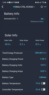
2. No they were at 77F today.

main.png

3. I agree from answering the previous reply lol. I'll look into fixing it.

4. I guess to clarify no I don't leave it running 24/7 when I'm not using it on a trip. If I'm out traveling in it though yes I leave it on for the duration of the trip. It runs the cooler with food in it so that's really the primary use.

Those points all make sense. Maybe it's just not sized appropriately to how I'm using it then. I'm not really sure if I'll make changes at this point. I think I'm going to fix the battery monitor and the battery wiring first before I do anything to drastic. I think I need to do some research on how to size a setup for my use case as well.

Yes, this could help significantly. There is a good chance that your top 2 batteries do not get much current flowing as the path of least resistance is the lowest battery.


When you disconnect to rewire, check the resting voltage of each battery after they've sat for a while. If you see a significant difference, you'll know this was an issue. If you were able to charge to completion with a significant absorb stage, there may be less of a difference.

I agree with others' opinions that you've run your batteries low.

Thanks I think I'll just go with using a bar and re doing the cabling. How would I know what type of bus bar to use? Do I use the battery max charge/discharge values as what Amperage to use for the bus bar?

The batteries are 50A (charging) and 80A (discharging) so would this 100A one work? I'll need to see what gauge the wire is though.
https://www.amazon.com/Blue-Sea-Systems-Common-Busbar

Or should I get something like this
https://www.amazon.com/Post-Power-Distribution-Block-Pair

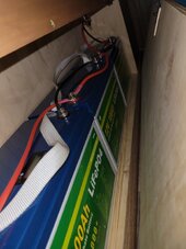
Here's the space they're in. I'm thinking I can mount it on the back wall.
20231226_100040.jpg
 
The amperage rating of the busbar should be greater than the maximum potential load current plus the maximum potential charge current.

At the very least you would want a 150A busbar, if not something that leaves some room to expand in the future, like 200-250A.
 
always shows the batteries at 100% so not sure how accurate it is or if it isn't connected correctly?
It's possible the monitor is not set up correctly.
Suggest the following,
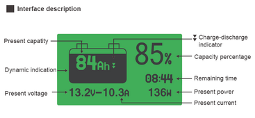
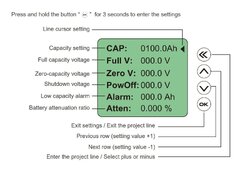
CAP 0300.0 Ah battery bank capacity
Full V 014.I V voltage considered to be fully charged, slightly lower than charge volts, this is the most important
Zero V 011.0 V voltage considered empty, should not be reached in normal operztion
PowOff 012.5 V display off, set as required
Alarm 012.0 V alarm, set as required
Atten 0.000 % not used

Screenshot_20231231-224523_Drive~2.jpg

Comment, there does not seem to be over current protection shown, fuses or breakers.

not sure if that's the actual use case for those load terminals?
The load terminals are not usually used in RV applications.
3 100ah LiFePO4 batteries
It's not clear that these batteries have low temperature protection in the BMS. I suspect these LF4160 do not have this low temperature protection thus care is needed not to charge below 0C, 32F, as the batteries will be damaged.
 
It's possible the monitor is not set up correctly.
Suggest the following,
CAP 0300.0 Ah battery bank capacity
Full V 014.I V voltage considered to be fully charged, slightly lower than charge volts, this is the most important
Zero V 011.0 V voltage considered empty, should not be reached in normal operztion
PowOff 012.5 V display off, set as required
Alarm 012.0 V alarm, set as required
Atten 0.000 % not used

View attachment 186117

Comment, there does not seem to be over current protection shown, fuses or breakers.


The load terminals are not usually used in RV applications.

It's not clear that these batteries have low temperature protection in the BMS. I suspect these LF4160 do not have this low temperature protection thus care is needed not to charge below 0C, 32F, as the batteries will be damaged.
I agree I don't think I set it up right. I think I have an older version though. Mine doesn't show Full V or Zero V options so that's why I'm thinking I have to do the full deplete/recharge to get it to read correctly.
 
I did a bit of redesign after reading through the book and guides which were very helpful but I have a few questions.

The PO didn't add any fuses other than to the DC appliances so I would like to add the recommended ones but I'm not certain if I've got them in the right place.
  • Should the 300A MEGA fuse be next to the battery or next to the inverter from how everything is connected to a bus bar?
  • Same question for the 50A circuit breaker for the MPTT. Is that the correct spot to add it closer to the MPTT?
  • For the 50A at the fuse panel I think because I'm not wiring it after the MEGA fuse it needs its own fuse correct? I'm not sure what type of fuse to use for this though?
    • Should it be an in line one like this 6 AWG Inline Fuse? Or would a bolt on fuse like a second MEGA fuse holder with a 50A fuse be better?
I'm planning on swapping all the cabling to 6 AWG other than the inverter cables I'm going to swap to 4/0 AWG.

van_diagram1.png

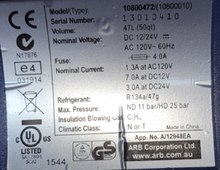
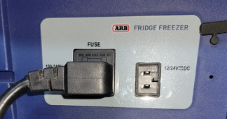
I also found that the cooler has both 120V and 12V plugs so I'd like to run it off 12V instead to save from having to run the inverter.
  • What would I use to plug into the cooler input for the 12v plug? I don't think I'm googling the right terms.
  • I was thinking I'd run a 10 AWG cable with a XT-60 end to where the cooler is about 7ft.
    • Then plug the cooler in to that once I figure out the right plug for the cooler.
    • Would a 15A fuse be a good size with the cooler using 7A and using 10 AWG cable?

cooler2.pngcooler1.png

I'd also like to check how the solar panels were wired if they are in two groups of series or not. Is the the voltage a good enough way to determine that or should I just pull the wiring and trace it? I think they are all 4 in series at the moment. I think I'd like to change it to 2 parallel groups of series as another future improvement.

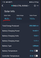
My thinking is I've seen voltage hit up to 70v from the panels so they have to be in series otherwise if they were in 2 groups you wouldn't see over 48v correct?

Here's where I'm getting the voltage I didn't catch the 70v I saw though it fluctuated before I took a screenshot.

solar.png
 
@jajao555
All your questions are answered in the set of 8 basic videos that Will Prowse, the owner of this forum, recorded for you to easily learn and answer these exact questions.
He has a video on:
What size wires
Where do I put the fuse?
What size fuse?
Parallel or series for my panels?
What size batteries?
Why are my batteries not charging?

Etc.
I recommend you take 45 min and watch his "Beginners Start Here!" Series. You will get faster answers, and better yet you will understand them.

Additionally, he has videos that have basically your EXACT SETUP, bolted to a board, even using the Renogy equipment! He goes through exactly how to build it. Where the fuses go.

The general answer to your questions is that the fuse protects the wire. So you usually place it BEFORE the wire, towards current source. The fuse is 120% or so of the wire ampacity. The wire is sized off the POSSIBLE load. All of it is done with a "worst case, this much current could possibly flow through here, if I mess something up..." So the battery/inverter fuse goes close to battery. The mppt fuse or breaker just goes on wire before the mppt SCC. Your DC should flow to a dc fuseblock, from the battery. All your dc loads hook up to the dc fuseblock where fuses protect them, including the 12v cooler.

Work through the videos he made specifically for you, and others in your situation. There are plenty of folks happy to help, but you will better use their time and answers if you have a few more basics under your belt.
Here is a link to the series.
 
Last edited:
15A fuse be a good size with the cooler using 7A and using 10 AWG cable?
Should be fine.
300A MEGA fuse be next to the battery
Next to the battery, MRBF in a Blue Sea holder direct on the battery post would be ideal.
50A circuit breaker for the MPTT. Is that the correct spot to add it closer to the MPTT?
Correct spot is next to the high power source, the positive buss bar.
cooler using 7A
That's a continious 7 amps unless it's a compressor driven cool box, 170 Ah per day.
50A at the fuse panel I
Near the buss bar, 50A midi fuse with holder.

Example system showing fuse location, ( the additional fuse for the Inverter is not needed in your system)
Screenshot_20230905-200359_Chrome~2.jpg
 
Back
Top