Hi, everybody! I'm a retired EE. I didn't want my EE skills to fade away after retirment, so I exercise them when I can. Whenever I see a non-trivial circuit analysis problem on one of various forums I frequent, I challenge myself to solve it. Recently I watched Will's video about current sharing in a parallel battery string, and it occurred to me that the string is just a circuit. It could be solved using standard circuit analysis techniques giving theoretical values for the battery currents. I wondered if this has been done before and posted on the web. I found a link on this forum to an article that gives numerical values: http://www.smartgauge.co.uk/batt_con.html This article solves a parallel string of 4 batteries with load connected in two ways--one case with the load connected at one end of the string and the other case using a diagonal connected load.
I decided to solve those two cases myself and compare my results with the results in the article. I drew up a model for the string and it turns out that
to completely solve the circuit takes 11 simultaneous equations, The article says its solution was done in about 1980, and the author says "the
calculation is incredibly difficult". Nowadays we have some very powerful mathematical software, so I knew that setting up the equations would be
the hard part; the actual number crunching would be easy since a computer would do it.
I set up the 11 equations and got a solution which I compared to the results in the article. My result was not the same at first, but having the
article's result to compare helped me track down my errors. I have got the equations right now. I don't want this thread to be a full on propellor head
thread, so I'm not going to post anything about the math; I'm only to give numerical results for a number of hookups and initial conditions. If anyone
wants to know about the math, ask and I'll do another thread.
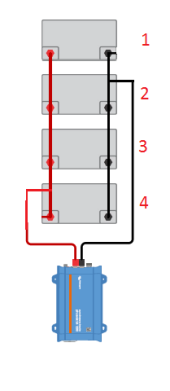
The values for the initial parameters for the 4 battery string used by the article are 20 milliohms for the battery internal resistance, 1.5 milliohms for
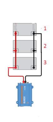
the link cable resistance, and a 100 amp load. For the first case with the load connected to one end of the string I got the following values for the
battery currents in amps:
35.8
26.1
20.4
17.7
These are the very same values given in the article except for 3 single digit differences; these tiny discrepancies are no doubt due to rounding errors
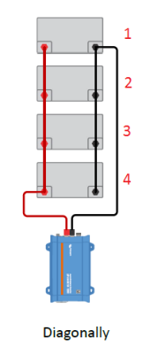
in the mathematical calculations. I changed my setup to solve for the battery currents for the second case--the load connected diagonally. Using the same initial parameters I got the following values for the battery currents in amps:
26.7
23.3
23.3
26.7
Again, I got the same values as the article with a couple of small rounding errors. Getting this good agreement with the values in the article gives me confidence that I have got my equations right!
I decided to solve those two cases myself and compare my results with the results in the article. I drew up a model for the string and it turns out that
to completely solve the circuit takes 11 simultaneous equations, The article says its solution was done in about 1980, and the author says "the
calculation is incredibly difficult". Nowadays we have some very powerful mathematical software, so I knew that setting up the equations would be
the hard part; the actual number crunching would be easy since a computer would do it.
I set up the 11 equations and got a solution which I compared to the results in the article. My result was not the same at first, but having the
article's result to compare helped me track down my errors. I have got the equations right now. I don't want this thread to be a full on propellor head
thread, so I'm not going to post anything about the math; I'm only to give numerical results for a number of hookups and initial conditions. If anyone
wants to know about the math, ask and I'll do another thread.
The values for the initial parameters for the 4 battery string used by the article are 20 milliohms for the battery internal resistance, 1.5 milliohms for
the link cable resistance, and a 100 amp load. For the first case with the load connected to one end of the string I got the following values for the
battery currents in amps:
35.8
26.1
20.4
17.7
These are the very same values given in the article except for 3 single digit differences; these tiny discrepancies are no doubt due to rounding errors
in the mathematical calculations. I changed my setup to solve for the battery currents for the second case--the load connected diagonally. Using the same initial parameters I got the following values for the battery currents in amps:
26.7
23.3
23.3
26.7
Again, I got the same values as the article with a couple of small rounding errors. Getting this good agreement with the values in the article gives me confidence that I have got my equations right!
")